


 286 / 356

D-38
Designing connections
u
630 A
between a device and busbars
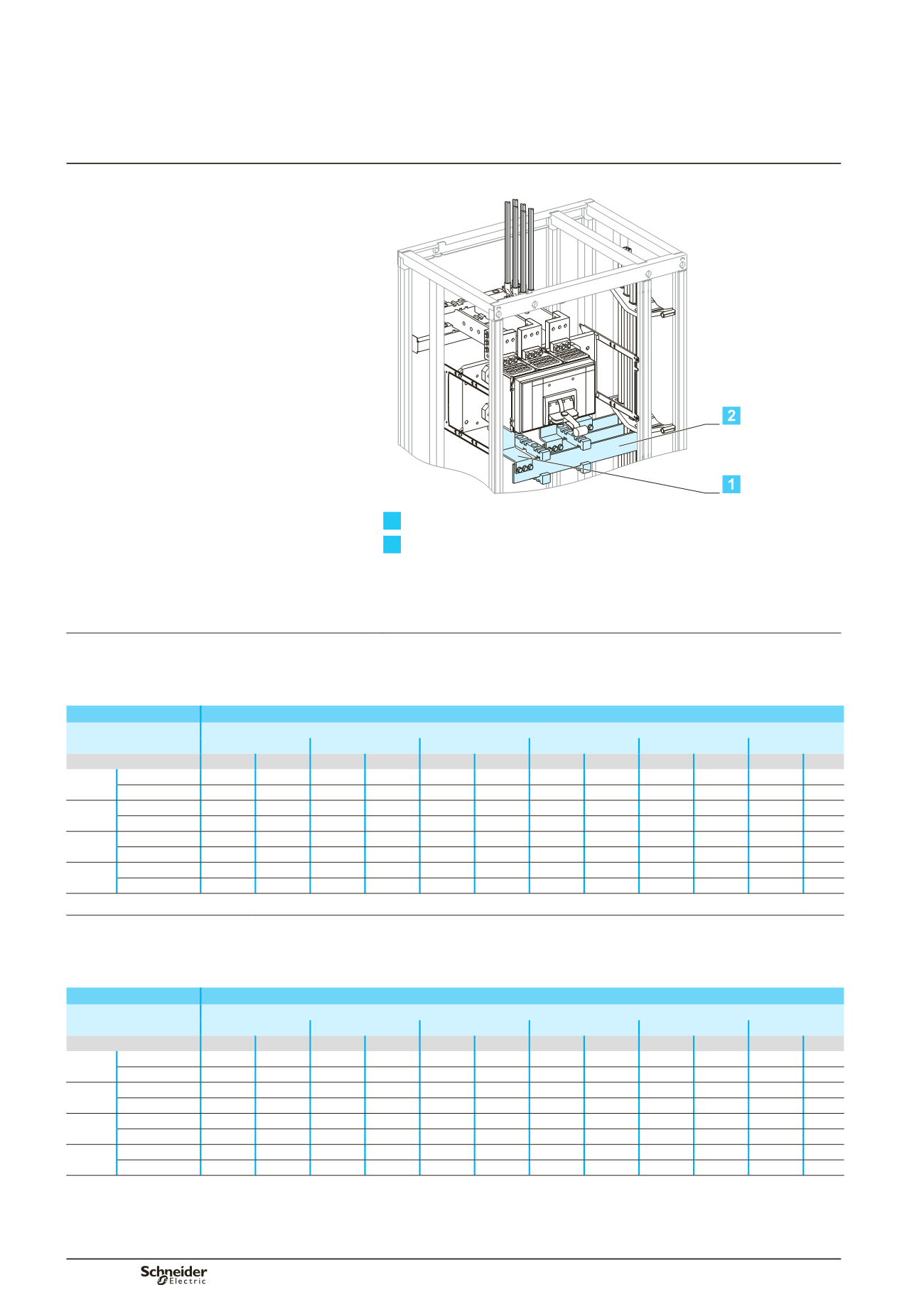
Fixed NS1600b to NS3200
Front or rear connection
Compact NS1600b/3200
Fixed, top or bottom connection
Dd383539
1
Connection.
2
Horizontal link.
Using the data below, it is possible to determine the size of the copper bars and the
maximum permissible currents when making the connections to busbars for a
vertical, fixed Compact NS1600b/3200, front or rear connection, taking into account
the ambient temperature around the switchboard and the IP value.
Connection
Flat bars, 10 mm thick
Device
Permissible current (A)
Ambient temperature around the switchboard
25 °C
30 °C
35 °C
40 °C
45 °C
50 °C
IP
y
31 IP > 31 IP
y
31 IP > 31 IP
y
31 IP > 31 IP
y
31 IP > 31 IP
y
31 IP > 31 IP
y
31 IP > 31
NS1600b Size per phase 1b 80 x 10 1b 80 x 10 1b 80 x 10 1b 80 x 10 1b 80 x 10 1b 80 x 10 1b 80 x 10 1b 80 x 10 1b 80 x 10 1b 80 x 10 1b 80 x 10
b
I (A)
1560
1480
1520
1430
1480
1380
1430
1330
1380
1280
1330
NS2000 Size per phase 2b 80 x 10 2b 80 x 10 2b 80 x 10 2b 80 x 10 2b 80 x 10 2b 80 x 10 2b 80 x 10 2b 80 x 10 2b 80 x 10 2b 80 x 10 2b 80 x 10
b
I (A)
2000
2000
2000
1950
2000
1900
1950
1830
1900
1760
1830
NS2500 Size per phase 2b 80 x 10 2b 80 x 10 2b 80 x 10 2b 80 x 10 2b 80 x 10 2b 80 x 10 2b 80 x 10 2b 80 x 10 2b 80 x 10 2b 80 x 10 2b 80 x 10
b
I (A)
2470
2280
2410
2210
2350
2140
2280
2070
2210
2000
2140
NS3200 Size per phase 3b 80 x 10 3b 80 x 10 3b 80 x 10 3b 80 x 10 3b 80 x 10 3b 80 x 10 3b 80 x 10 3b 80 x 10 3b 80 x 10 3b 80 x 10 3b 80 x 10
b
I (A)
2860
2630
2790
2530
2720
2430
2630
2350
2530
2270
2430
Horizontal link
Flat bars, 10 mm thick
Device
Permissible current (A)
Ambient temperature around the switchboard
25 °C
30 °C
35 °C
40 °C
45 °C
50 °C
IP
y
31 IP > 31 IP
y
31 IP > 31 IP
y
31 IP > 31 IP
y
31 IP > 31 IP
y
31 IP > 31 IP
y
31 IP > 31
NS1600b Size per phase 1b 80 x 10 1b 80 x 10 1b 80 x 10 1b 80 x 10 1b 80 x 10 1b 80 x 10 1b 80 x 10 1b 80 x 10 1b 80 x 10 1b 80 x 10 1b 80 x 10
b
I (A)
1560
1480
1520
1430
1480
1380
1430
1330
1380
1280
1330
NS2000 Size per phase 2b 60 x 10 2b 60 x 10 2b 60 x 10 2b 60 x 10 2b 60 x 10 2b 60 x 10 2b 60 x 10 2b 60 x 10 2b 60 x 10 2b 60 x 10 2b 60 x 10
b
I (A)
2000
2000
2000
1950
2000
1900
1950
1830
1900
1760
1830
NS2500 Size per phase 2b 80 x 10 2b 80 x 10 2b 80 x 10 2b 80 x 10 2b 80 x 10 2b 80 x 10 2b 80 x 10 2b 80 x 10 2b 80 x 10 2b 80 x 10 2b 80 x 10
b
I (A)
2470
2280
2410
2210
2350
2140
2280
2070
2210
2000
2140
NS3200 Size per phase 2b100 x 10 2b100 x 10 2b100 x 10 2b100 x 10 2b100 x 10 2b100 x 10 2b100 x 10 2b100 x 10 2b100 x 10 2b100 x 10 2b100 x 10
b
I (A)
2860
2630
2790
2530
2720
2430
2630
2350
2530
2270
2430
b
connection not possible.
Note:
the values indicated above have been validated for Prisma Plus switchboards.
Additional informations
Designing electrical
characteristics