


 291 / 356

D-43
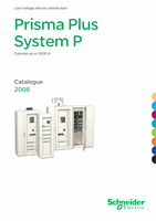
Compact NS630b to NS1600
Horizontal, fixed
Dd383538
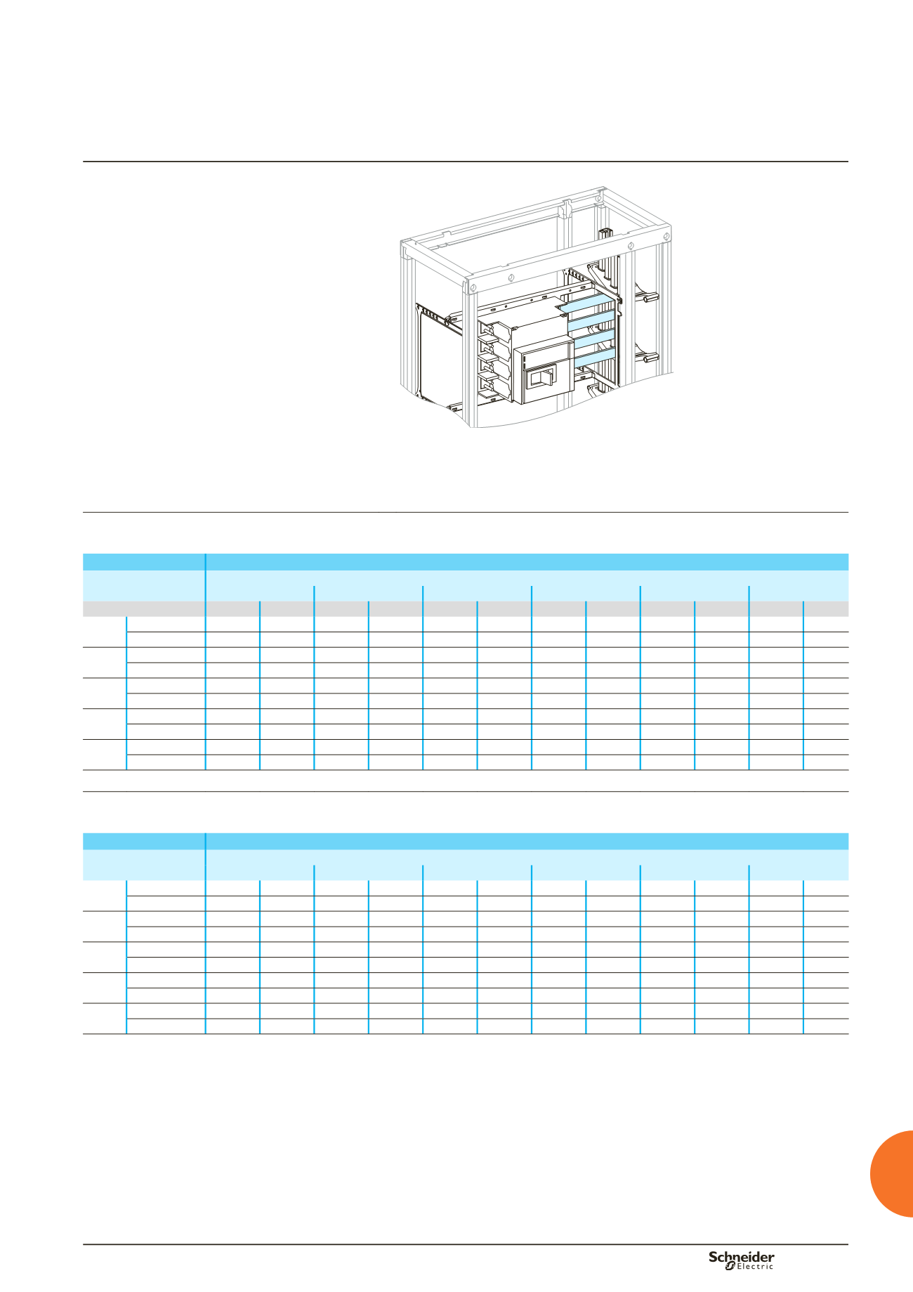
Using the data below, it is possible to determine the size of the copper bars and the
maximum permissible currents when making the connections to busbars for a
horizontal, fixed Compact NS630b/NS1600, taking into account the ambient
temperature around the switchboard and the IP value.
Flat bars, 5 mm thick
Device
Permissible current (A)
Ambient temperature around the switchboard
25 °C
30 °C
35 °C
40 °C
45 °C
50 °C
IP
y
31 IP > 31 IP
y
31 IP > 31 IP
y
31 IP > 31 IP
y
31 IP > 31 IP
y
31 IP > 31 IP
y
31 IP > 31
NS630b Size per phase 2b 50 x 5 2b 50 x 5 2b 50 x 5 2b 50 x 5 2b 50 x 5 2b 50 x 5 2b 50 x 5 2b 50 x 5 2b 50 x 5 2b 50 x 5 2b 50 x 5
b
I (A)
630
630
630
630
630
630
630
630
630
630
630
NS800 Size per phase 2b 50 x 5 2b 50 x 5 2b 50 x 5 2b 50 x 5 2b 50 x 5 2b 50 x 5 2b 50 x 5 2b 50 x 5 2b 50 x 5 2b 50 x 5 2b 50 x 5
b
I (A)
800
800
800
800
800
800
800
800
800
800
800
NS1000 Size per phase 2b 50 x 5 2b 50 x 5 2b 50 x 5 2b 50 x 5 2b 50 x 5 2b 50 x 5 2b 50 x 5 2b 50 x 5 2b 50 x 5 2b 50 x 5 2b 50 x 5
b
I (A)
1000
1000
1000
1000
1000
1000
1000
1000
1000
1000
1000
NS1250 Size per phase 3b 50 x 5 3b 50 x 5 3b 50 x 5 3b 50 x 5 3b 50 x 5 3b 50 x 5 3b 50 x 5 3b 50 x 5 3b 50 x 5
b
3b 50 x 5
b
I (A)
1250
1250
1250
1250
1250
1170
1250
1090
1170
1000
NS1600 Size per phase 4b 50 x 5 4b 50 x 5 4b 50 x 5 4b 50 x 5 4b 50 x 5 4b 50 x 5 4b 50 x 5 4b 50 x 5 4b 50 x 5
b
4b 50 x 5
b
I (A)
1600
1510
1560
1470
1510
1420
1470
1360
1420
1360
Flat bars, 10 mm thick
Device
Permissible current (A)
Ambient temperature around the switchboard
25 °C
30 °C
35 °C
40 °C
45 °C
50 °C
NS630b Size per phase 1b 50 x 10 1b 50 x 10 1b 50 x 10 1b 50 x 10 1b 50 x 10 1b 50 x 10 1b 50 x 10 1b 50 x 10 1b 50 x 10 1b 50 x 10 1b 50 x 10
b
I (A)
630
630
630
630
630
630
630
630
630
630
630
NS800 Size per phase 1b 50 x 10 1b 50 x 10 1b 50 x 10 1b 50 x 10 1b 50 x 10 1b 50 x 10 1b 50 x 10 1b 50 x 10 1b 50 x 10 1b 50 x 10 1b 50 x 10
b
I (A)
800
800
800
800
800
800
800
800
800
800
800
NS1000 Size per phase 1b 50 x 10 1b 50 x 10 1b 50 x 10 1b 50 x 10 1b 50 x 10 1b 50 x 10 1b 50 x 10 1b 50 x 10 1b 50 x 10 1b 50 x 10 1b 50 x 10
b
I (A)
1000
1000
1000
1000
1000
1000
1000
1000
1000
1000
1000
NS1250 Size per phase 2b 50 x 10 2b 50 x 10 2b 50 x 10 2b 50 x 10 2b 50 x 10 2b 50 x 10 2b 50 x 10 2b 50 x 10 2b 50 x 10
b
2b 50 x 10
b
I (A)
1250
1250
1250
1250
1250
1170
1250
1090
1170
1090
NS1600 Size per phase 2b 50 x 10 2b 50 x 10 2b 50 x 10 2b 50 x 10 2b 50 x 10 2b 50 x 10 2b 50 x 10 2b 50 x 10 2b 50 x 10
b
2b 50 x 10
b
I (A)
1600
1510
1560
1470
1510
1420
1470
1360
1420
1360
b
connection not possible.
Note:
the values indicated above have been validated for Prisma Plus switchboards.
Designing connections
u
630 A
between a device and busbars
Compact circuit breakers
Horizontal, fixed NS630b to NS1600
Additional informations
Designing electrical
characteristics