


 296 / 356

D-48
Size of PE protective conductor
Practical guidelines
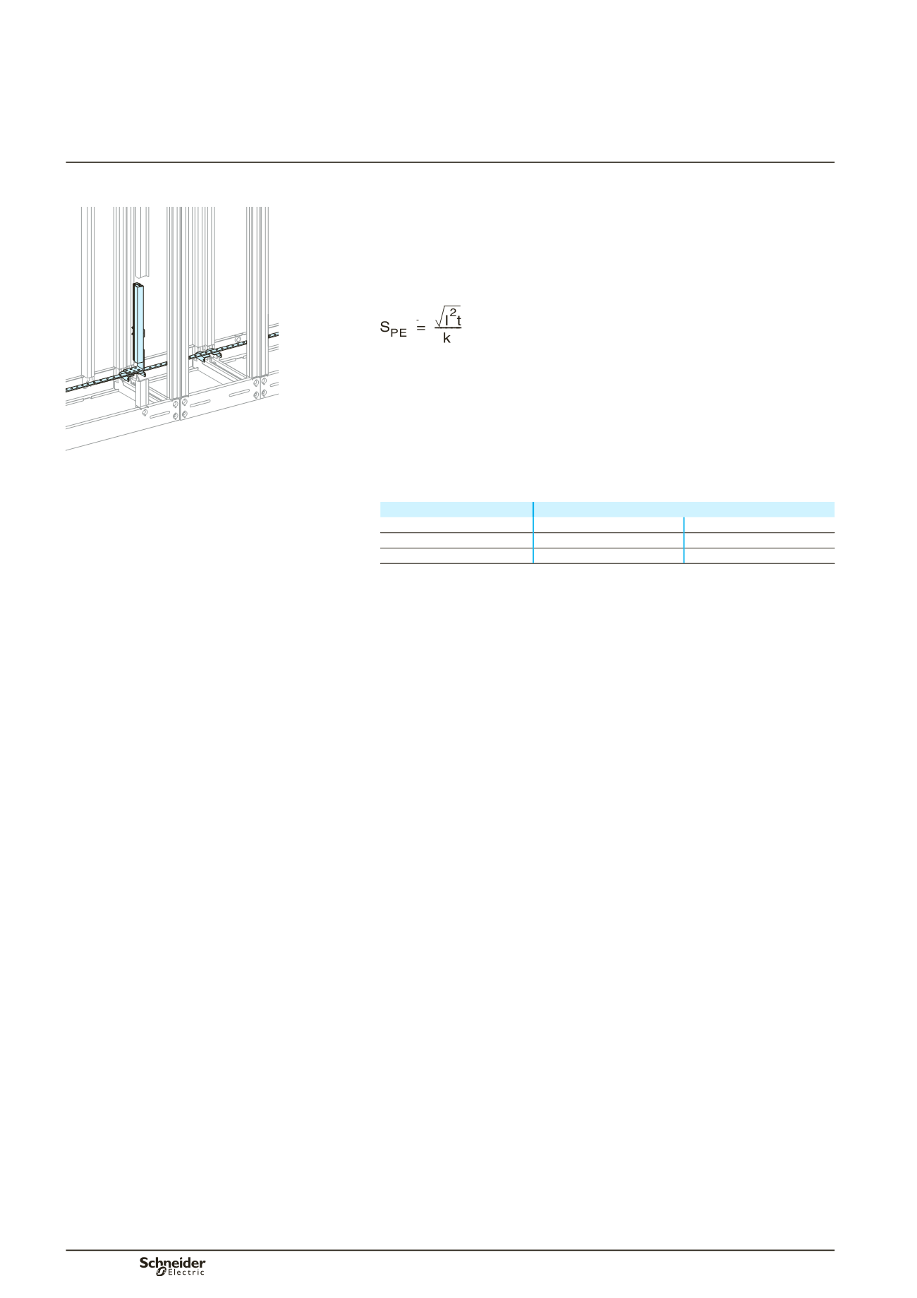
The conductor must be sufficiently sized and securely installed in the switchboard to
accept the thermal and electrodynamic stresses of the fault current.
It must be connected to the exposed conductive parts of the switchboard.
It must be access ble to enable connections both in the factory and on site.
Optimised calculation method
Use the calculation equation indicated in standard IEC 60439-1.
S
pe
: cross-sectional area of PE in mm
2
I
: value of the phase-to-earth fault current = 60 % of the value of the phase-to-
phase fault current (IEC 60439-1 §8.2.4.2)
t
: time the fault current flows in seconds
k
: coefficient that depends on the type of metal, k = 143 for a copper conductor
with PVC insulation.
Simplified method (based on the equation above)
Use the table below to determine the size of the PE conductor as a function of the
device Isc.
b
b
b
b
DD381471
Size of PE conductor
All Schneider Electric devices
Isc
y
40 kA
1 bar, 25 x 5 mm
Linergy 630
Isc
y
65 kA
1 bar, 50 x 5 mm
Linergy 630
Isc > 65 kA
1 bar, 50 x 5 mm
Linergy 800
Schneider Electric prefabricated solution
For all Schneider Electric devices for an Isc up to 85 kA: see page B-72.
Designing the PE
protective conductor
Power circuit
Additional informations
Designing electrical
characteristics