


 301 / 356

D-53
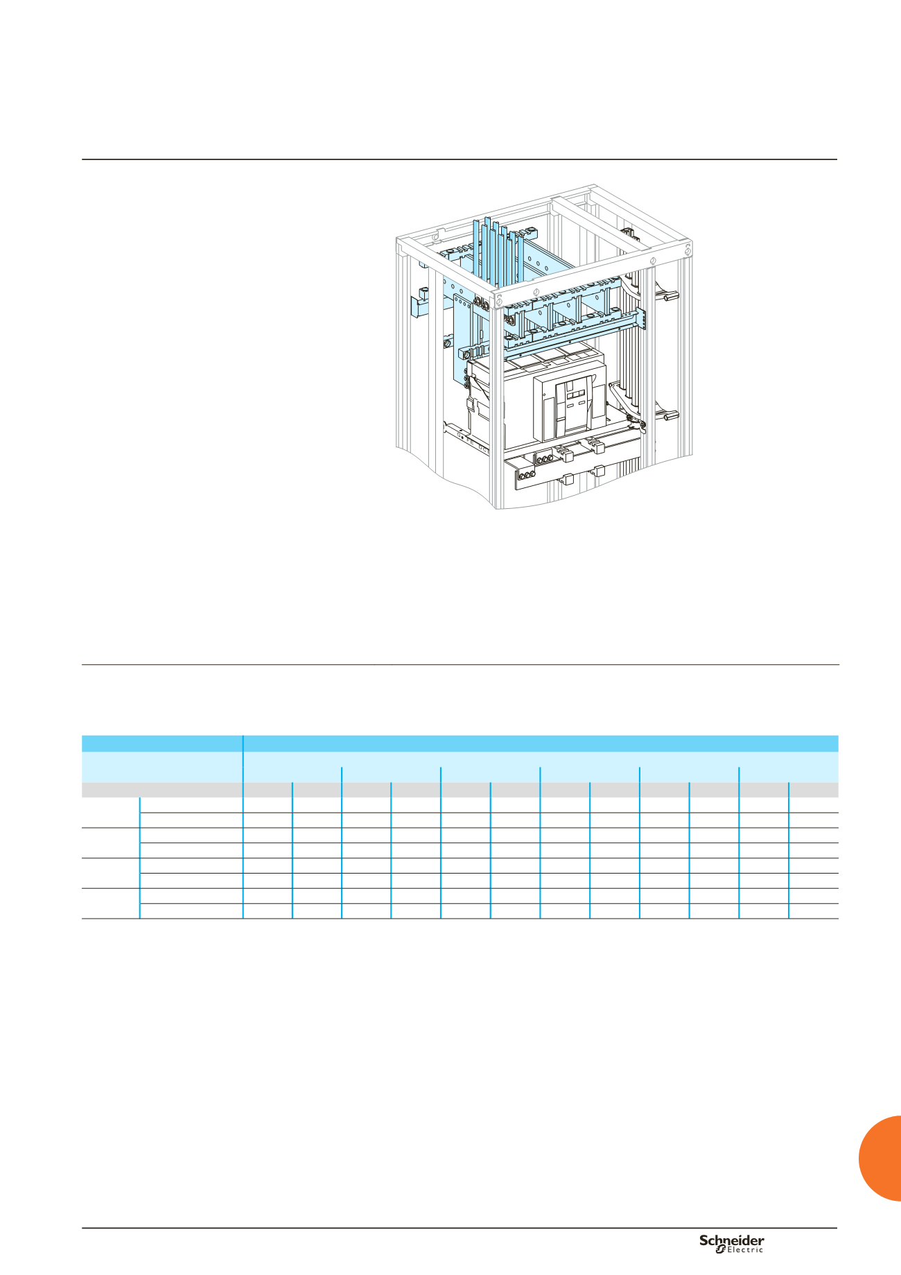
Masterpact NW08 to NW32
Fixed, top or bottom connection
DD383674
Using the data below, it is possible to determine the size of the copper bars and the
maximum permissible currents when making a front or rear customer connection for
a vertical, fixed NW08/NW32, taking into account the ambient temperature around
the switchboard and the IP value.
Connection to be made according to the busbar drawings supplied.
For connection cable cross-sections and quantities, see page D-46.
Customer connection
Flat bars, 5 mm thick
Devices
Permissible current (A)
Ambient temperature around the switchboard
25 °C
30 °C
35 °C
40°C
45 °C
50 °C
IP
y
31 IP > 31 IP
y
31 IP > 31 IP
y
31 IP > 31 IP
y
31 IP > 31 IP
y
31 IP > 31 IP
y
31 IP > 31
NW08
Size per phase
2b 60 x 5 2b 60 x 5 2b 60 x 5 2b 60 x 5 2b 60 x 5 2b 60 x 5 2b 60 x 5 2b 60 x 5 2b 60 x 5 2b 60 x 5 2b 60 x 5
b
I (A)
800
800
800
800
800
800
800
800
800
800
800
NW10
Size per phase
2b 60 x 5 2b 60 x 5 2b 60 x 5 2b 60 x 5 2b 60 x 5 2b 60 x 5 2b 60 x 5 2b 60 x 5 2b 60 x 5 2b 60 x 5 2b 60 x 5
b
I (A)
1000 1000 1000 1000 1000 1000 1000 1000 1000 1000 1000
NW12
Size per phase
2b 80 x 5 2b 80 x 5 2b 80 x 5 2b 80 x 5 2b 80 x 5 2b 80 x 5 2b 80 x 5 2b 80 x 5 2b 80 x 5 2b 80 x 5 2b 80 x 5
b
I (A)
1250 1250 1250 1250 1250 1250 1250 1250 1250 1250 1250
NW16
Size per phase
2b 80 x 5 2b 80 x 5 2b 80 x 5 2b 80 x 5 2b 80 x 5 2b 80 x 5 2b 80 x 5 2b 80 x 5 2b 80 x 5 2b 80 x 5 2b 80 x 5
b
I (A)
1600 1600 1600 1570 1600 1520 1570 1470 1520 1420 1470
b
connection not possible.
Note:
the values indicated above have been validated for Prisma Plus switchboards.
Designing customer
connections
Fixed Masterpact NW08 to NW32
Front or rear connection
Additional informations
Designing electrical
characteristics