


 67 / 338

A-15
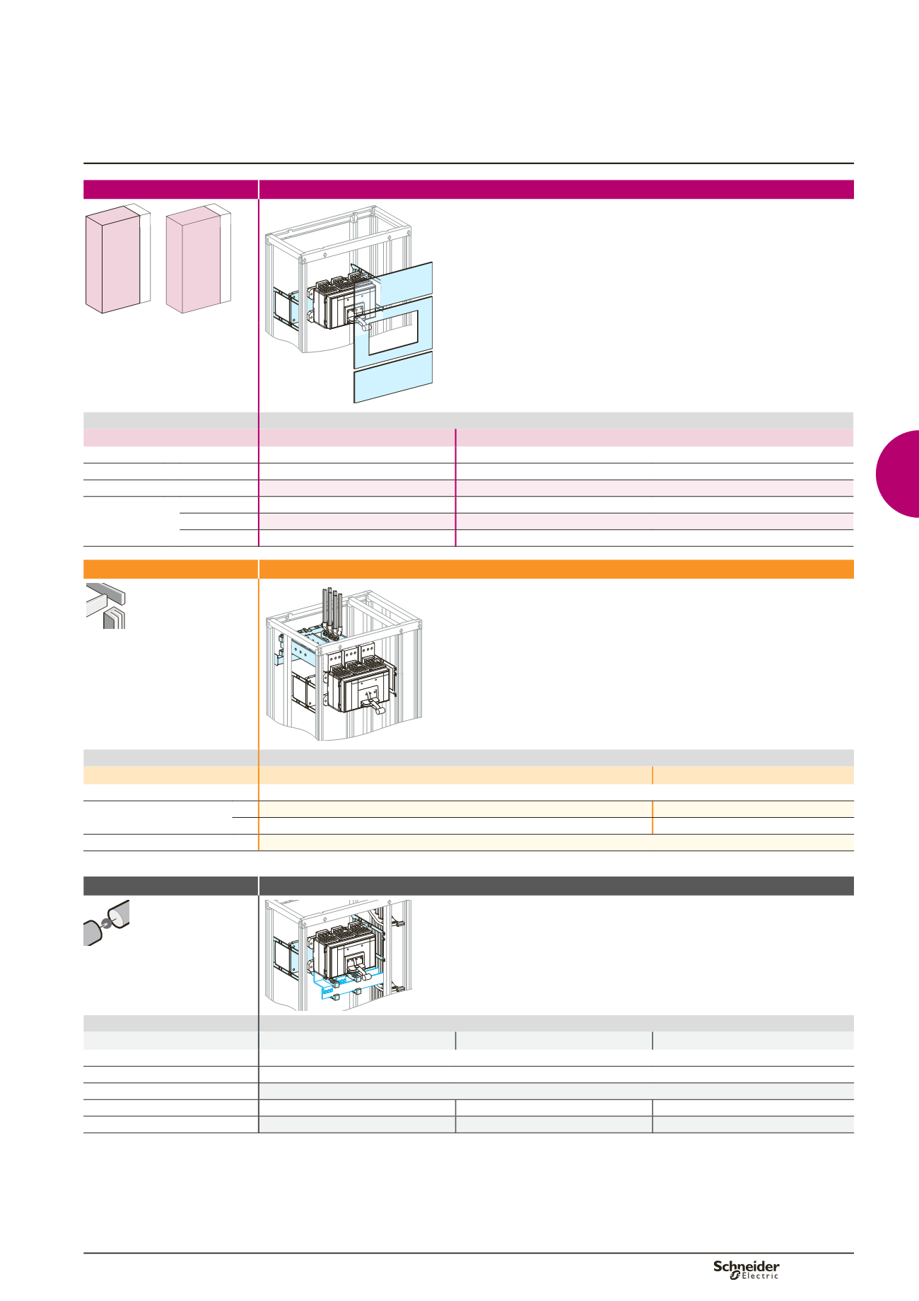
Compact NS1600b to 3200
Cables connection
Circuit breakers
Functional system
Functional units
Mounting
Front connection
650 150
400
650 150
600
Dd385439.eps
NS1600b
NS2000/3200
Devices
Fixed device
NS1600b
NS2000/3200
Number of devices per row
1
1
No. of vertical modules
14
16
Mounting plates
03501
03501
Front plates
[No. of vertical
modules]
upstream
03802
[2]
03802
[2]
with cut-out
03716
[8]
03716
[8]
downstream
03804
[4]
03806
[6]
Connection
Upstream on incomer
Dd385440.eps
Devices
Fixed device
NS1600b/2500
NS3200
Type of terminals
Front connections supplied with the device
Vertical-connection adapters 3P
33975
(1)
33975
(1)
4P
33976
(1)
33976
(1)
Terminal extension bar support
04694
(1)
Connection to be made according to the busbar drawings supplied by Schneider Electric.
Distribution
Downstream on Linergy LGY, LGYE or BS busbars
Dd383548.eps
Devices
Fixed device
NS1600b
NS2000/2500
NS3200
Type of terminals
Front connections supplied with the device
Busbars connection
Must be made
(2) (3)
Free support for busbars connection 2 x
04662
Cover for busbars connection
04926
04926
04926
Additional cover
-
04927
04927
(2)
For the connection to flat busbars > 1600 A, order one joint per phase:
b
1 joint for busbars, W = 50/60 mm (04640)
b
1 joint for busbars, W = 80/100 mm (04641)
(3)
Connection to be made according to the busbar drawings supplied by Schneider Electric.
Note:
to make measurements:
b
install the CTs on the horizontal busbars (busbar connection); in this case, an additional module is required; add a plain front plate (03801)
b
or install a Micrologic control unit capable of displaying the values.
Selection of Linergy LGY:
see page B-14,
Linergy LGYE:
see page B-15,
Linergy BS:
see page B-16.