


 70 / 338

A-18
Compact NS630b to NS1000
Horizontal mounting
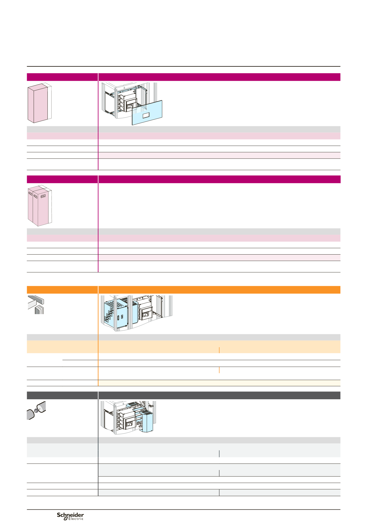
Toggle and rotary handle
Circuit breakers
Mounting
Front connection
650 150
400
Dd383551.eps
Devices
Fixed device
NS630b/1000
Number of devices per row
1
No. of vertical modules
7
(1)
Mounting plates
03480
Front plates with cut-outs
[No. of vertical modules]
03687
[7]
Mounting
Rear connection
150
Devices
Fixed device
NS630b/1000
Number of devices per row
1
No. of vertical modules
7
(1)
Mounting plates
03480
Front plates with cut-outs
[No. of vertical modules]
03687
[7]
(1)
Mounting of 03480 + connection transfert assembly 04483 or 04484 needs 8 vertical modules (use of one complementary front plate 1 module 03801) at the
bottom of the functional unit.
Connection
Upstream on incomer
Dd383550.eps
Devices
Fixed device
NS630b/1000
3P
4P
Type of terminals front connection Front connections supplied with the device
rear connection Vertical rear connections supplied with the device
Connection transfer assembly
04483
04484
Three 300 mm² or six 185 mm² cables can be connected per phase with lugs that are not of the two-metal type.
Cover rear connection
04844
Distribution
Downstream on Linergy LGY, LGYE or BS busbars
Dd383552.eps
Devices
Fixed device
NS630b/1000
3P
4P
Type of terminals
Front connections supplied with the device
Busbars connection
For Linergy LGY busbars: prefabricated connection
04473
04474
must be made
(1)
.
For Linergy LGYE (see page B-19) and Linergy BS busbars
Cover for busbars connection
04842
Arc-chute cover
33596
33597
(2)
Connection to be made according to the busbar drawings supplied by Schneider Electric.
Selection of Linergy LGY:
see page B-14,
Linergy LGYE:
see page B-15,
Linergy BS:
see page B-16.
Functional system
Functional units