


 63 / 338

A-11
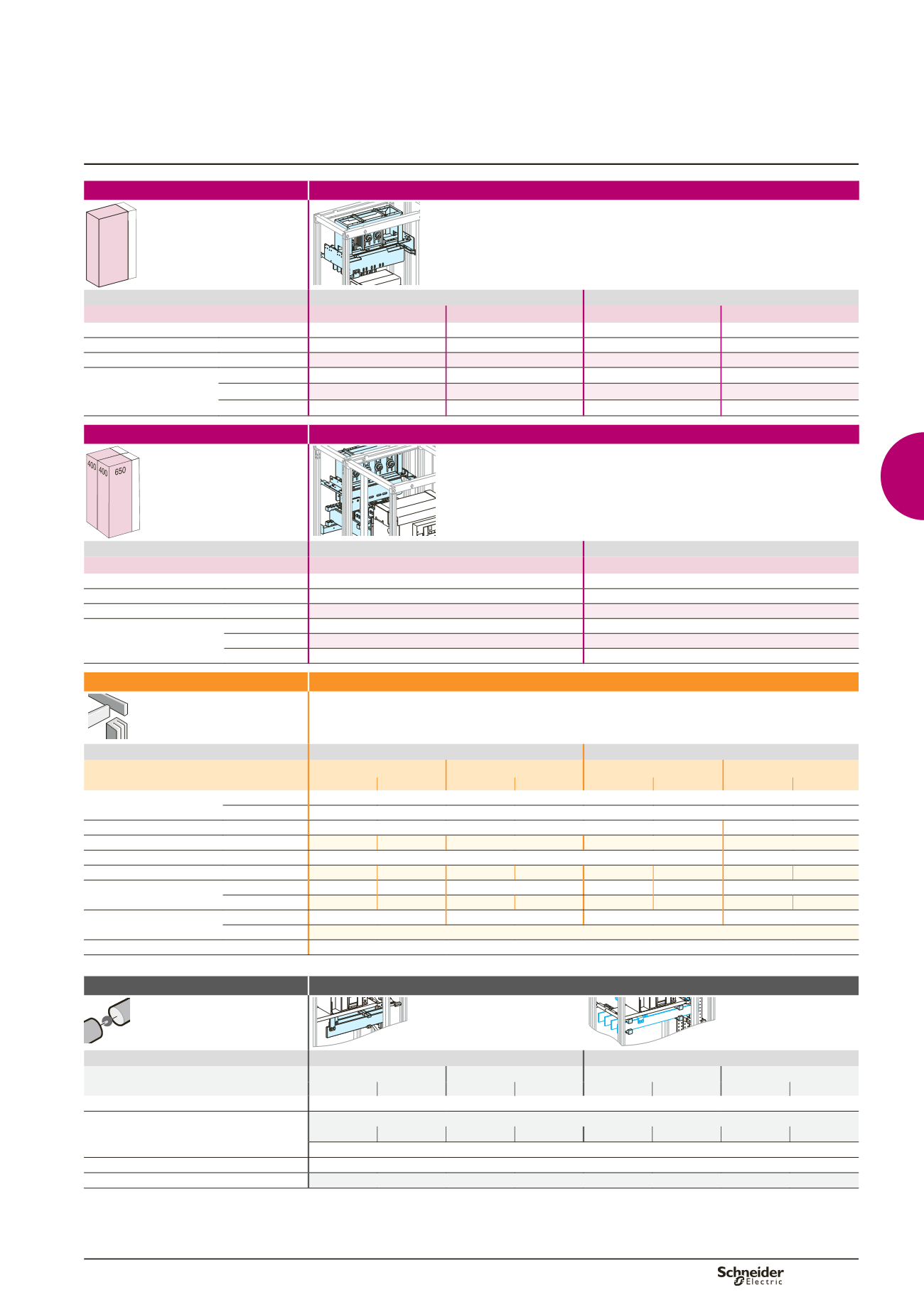
Mounting
Canalis front connection
650 150
400
Dd380795.eps
Devices
Fixed device
Withdrawable device
NT06/12
NT16
NT06/12
NT16
Number of devices per row
1
-
1
-
No. of vertical modules
17
-
18
-
Mounting plates
03484
-
03483
-
Front plates
[No. of vertical modules]
upstream
03804
[4]
+ 03803
[3]
-
03804
[4]
+ 03803
[3]
-
with cut-out
03692
[7]
-
03691
[8]
-
downstream
03803
[3]
-
03803
[3]
-
Mounting
Canalis rear connection
150
Dd383683.eps
Devices
Fixed device
Withdrawable device
NT06/16
NT06/16
Number of devices per row
1
1
No. of vertical modules
16
16
Mounting plates
03484
03483
Front plates
[No. of vertical modules]
upstream
03806
[6]
03805
[5]
with cut-out
03692
[7]
03691
[8]
downstream
03803
[3]
03803
[3]
Connection
Upstream on incomer
Devices
Fixed device
Withdrawable device
NT06/12
NT16
NT06/12
NT16
3P
4P
3P
4P
3P
4P
3P
4P
Type of terminals
front connection Front connections supplied with the device
rear connection Vertical rear connections supplied with the device
Terminal extension bar support rear connection 2 x
04693
-
Arc-chute cover
47335
47336
-
-
-
Canalis support
03561
-
Canalis interface
04703
04704
04703
04704
04703
04704
04703
04704
Canalis/device connection front connection
04711
04712
-
04711
04712
-
rear connection
04713
04714
04713
04714
04713
04714
04713
04714
Canalis cover
front connection
04871
+
04852
-
04871
+
04852
-
rear connection
04871
+
04854
Connection
must be made
(1)
on rear connection
(1)
Connection to be made according to the busbar drawings supplied by Schneider Electric.
Distribution
Downstream on Linergy LGY, LGYE or BS busbars
DD380648.eps
DD380649.eps
Devices
Fixed device
Withdrawable device
NT06/12
NT16
NT06/12
NT16
3P
4P
3P
4P
3P
4P
3P
4P
Type of terminals
Front connections supplied with the device
Busbars connection
For Linergy LGY busbars: prefabricated connection
04475
04476
04489
04490
04477
04478
04491
04492
must be made
(1)
.
For Linergy LGYE (see page B-19) and Linergy BS busbars
Free support for busbars connection
For flat busbars: 2 x
04662
Cover for busbars connection
04926
(1)
Connection to be made according to the busbar drawings supplied by Schneider Electric.
Note:
to make measurements:
b
install the CTs on the horizontal busbars (busbar connection); in this case, an additional module is required; add a plain front pla
te (03801)
b
or install a Micrologic control unit capable of displaying the values.
Selection of Linergy LGY:
see page B-14,
Linergy LGYE:
see page B-15,
Linergy BS:
see page B-16.
Masterpact NT06 to NT16
Toggle and motor mechanism
Canalis connection
Circuit breakers
Functional system
Functional units