


 58 / 338

A-6
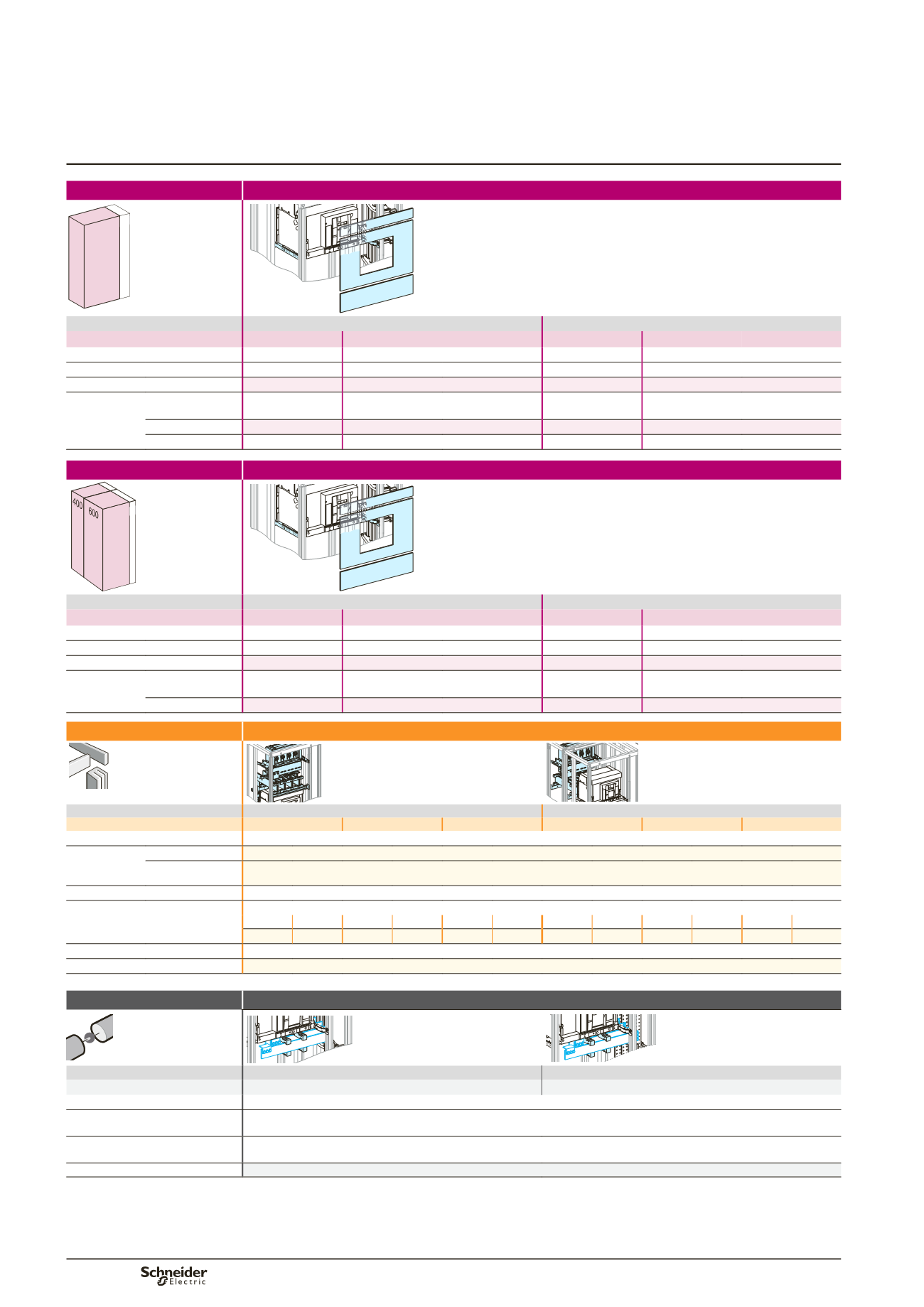
Masterpact NW08 to 32
Canalis connection
Mounting
Front connection
650 150
600
Dd383686.eps
Devices
Fixed device
Withdrawable device
NW08/16
NW20/32
NW08/16
NW20/32
Number of devices per row
1
1
1
1
No. of vertical modules
27
28
27
28
Mounting plates
03500
03500
03500
03500
Front plates
[No. of vertical
modules]
upstream
03805
[5]
2 x
03804
[8]
2 x
03805
[10]
03804
[4]
3 x
03804
[12]
03805
[5]
2 x
03804
[8]
with cut-out
03711
[9]
03711
[9]
03710
[10]
03710
[10]
downstream
03805
[5]
03805
[5]
03805
[5]
03805
[5]
Mounting
Rear connection
150
650
Dd383686.eps
Devices
Fixed device
Withdrawable device
NW08/16
NW20/32
NW08/16
NW20/32
Number of devices per row
1
1
1
1
No. of vertical modules
16
16
17
17
Mounting plates
03500
03500
03500
03500
Front plates
[No. of vertical
modules]
upstream
03804
[4]
+
03803
[3]
03804
[4]
+
03803
[3]
03804
[4]
+
03803
[3]
03804
[4]
+
03803
[3]
with cut-out
03711
[9]
03711
[9]
03710
[10]
03710
[10]
Connection
Upstream on incomer
Dd383681.eps
Dd383683.eps
Devices
Fixed device
Withdrawable device
NW08/16
NW20/25
NW32
NW08/16
NW20/25
NW32
Type of terminals
Vertical rear connections supplied with the device
Terminal
extension bar
support
for front connection 2 x
04694
+
04678
for rear connection 2 x
04694
Canalis support
03561
Connection
Canalis/device interface + connection (terminal extension bar support must be made)
(1)
3P
4P
3P
4P
3P
4P
3P
4P
3P
4P
3P
4P
04715 04716 04725 04726 04735 04736 04715 04716 04725 04726 04735 04736
Canalis cover front connection
04871
+
04861
Canalis cover rear connection
04871
+
04863
(1)
Connection to be made according to the busbar drawings supplied by Schneider Electric.
Distribution
Downstream on Linergy LGY, LGYE or BS busbars
Dd383687.eps
DD383808.eps
Devices
Fixed device
Withdrawable device
NW08/32
NW08/32
Type of terminals
Front connections supplied with the device
Busbars connection
must be made
(1)
. For the connection to flat busbars > 1600A, order one joint per phase: 1 joint for busbars, W = 50/60 mm
(04640), 1 joint for busbars, W = 80/100 mm (04641). For the connection to Linergy LGYE busbars, see
page B-19
Free support for busbars connection 2 x
04662
For Icw
u
75 kA rms, add an additional free support
04662
Cover for busbars connection
04926
+
04927
(1)
Connection to be made according to the busbar drawings supplied by Schneider Electric.
(2)
For LGYE 08/25, use a duct W = 150 mm. For LGYE 32/40, use a duct W = 300 mm.
Note:
to make measurements:
b
install the CTs preferably upstream, on the supply terminal extension bars or install the CTs on the horizontal busbars (busbar connection).. In this case, add one
module and a plain front plate (03801) or install a Micrologic control unit capable of displaying the values.
Selection of Linergy LGY:
see page B-14,
Linergy LGYE:
see page B-15,
Linergy BS:
see page B-16.
Circuit breakers
Functional system
Functional units