


 165 / 338

B-31
Linergy FC
Feeders for Compact NSX and INS
Distribution
Device feeders
Accessories
DD383594-LIN-100.eps
PB502509-18_r.eps
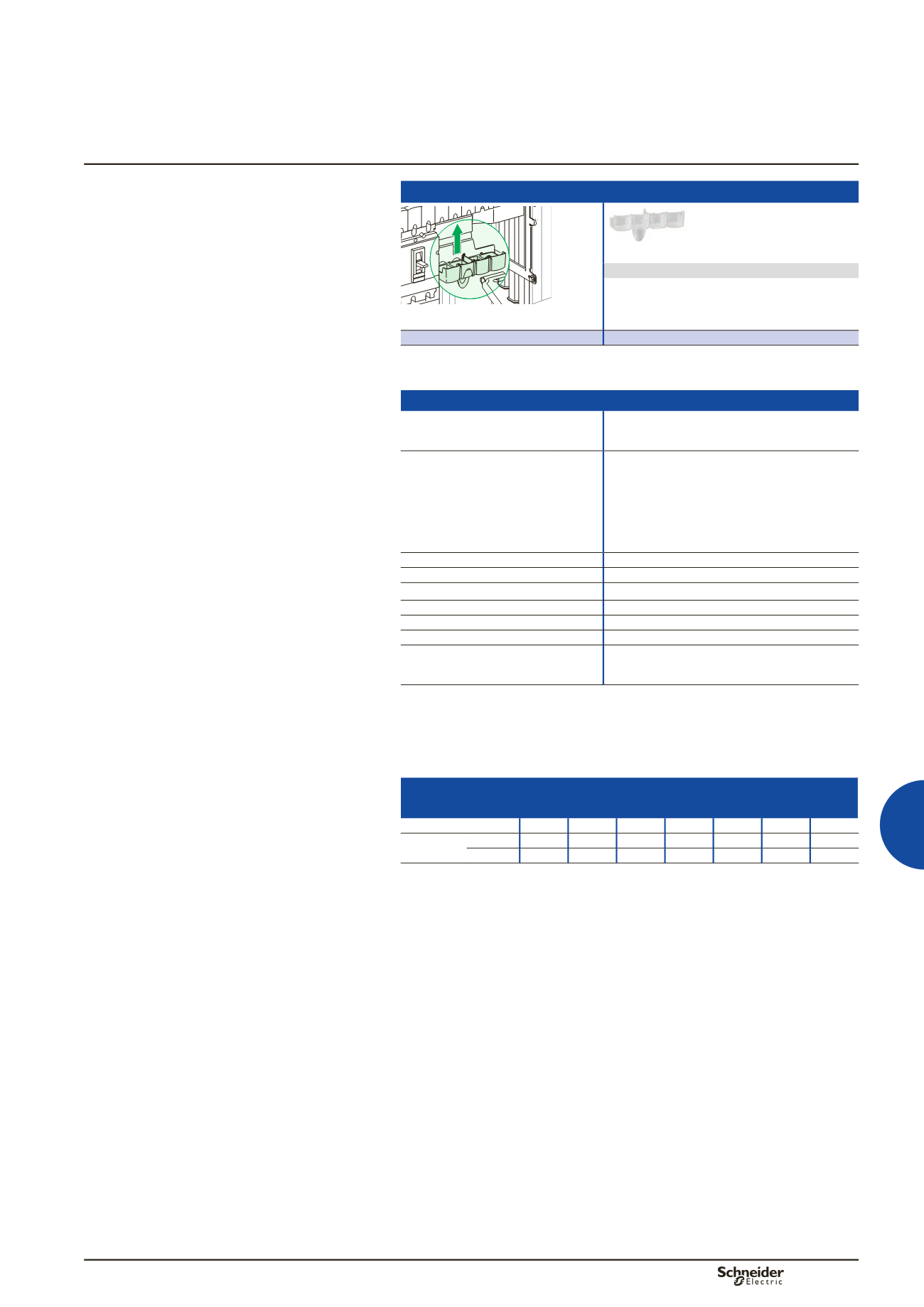
Tooth caps
The caps block off the reserve terminals on a
Linergy FC distribution block.
Made of an insulating material, they simply clip on
from the front.
Catalogue numbers
04809
Characteristics
Common characteristics
Rated operational current at 40° (Ie)
Distribution-block derating follows the normal
derating curves of Compact NSX and INS
Rated conditional short-circuit
current of an assembly
(Isc)
The reinforced breaking capacity due to cascading
in circuit-breaker combinations is maintained.
The worst-case situations have been tested.
The electrical characteristics are perfectly
compatible with the connected devices.
Neither the temperature derating curves nor the
performance levels of the circuit breakers and
switch-disconnectors are altered.
Rated insulation voltage
(Ui)
750 V AC
Rated operational voltage
(Ue)
690 V AC
Rated impulse withstand voltage (Uimp) 8 kV
Rated peak withstand current
(Ipk)
50 k rms
Rated short-time current
(Icw)
8.5 kA rms/1 s
Thermal stress
(A².s)
2.500 x 10
7
Rated conditional short-circuit current of
an assembly
Short-circuit withstand current compatible with the
breaking capacity of the Compact NSX circuit
breakers connected to the distribution block.
Linergy FC selection table for special cases
For most installations, the temperature around the switchboard is 40 °C,
corresponding to an average temperature of 60 °C inside the switchboard.
Under certain conditions, the temperature inside the switchboard may be different.
(A) Rated operational current as a function of the temperature
inside the switchboard
Temperature (°C)
40
45
50
55
60
65
70
I
nc
(A)
3P
800
800
775
750
725
700
675
4P
675
675
655
635
615
595
570
To obtain the maximum permissible current for the linergy FC, apply the diversity
factor K:
b
b
Linergy FC 3P: K = 0.8
b
b
Linergy FC 4P: RDF = 0.9.