


 160 / 338

B-26
Linergy BS
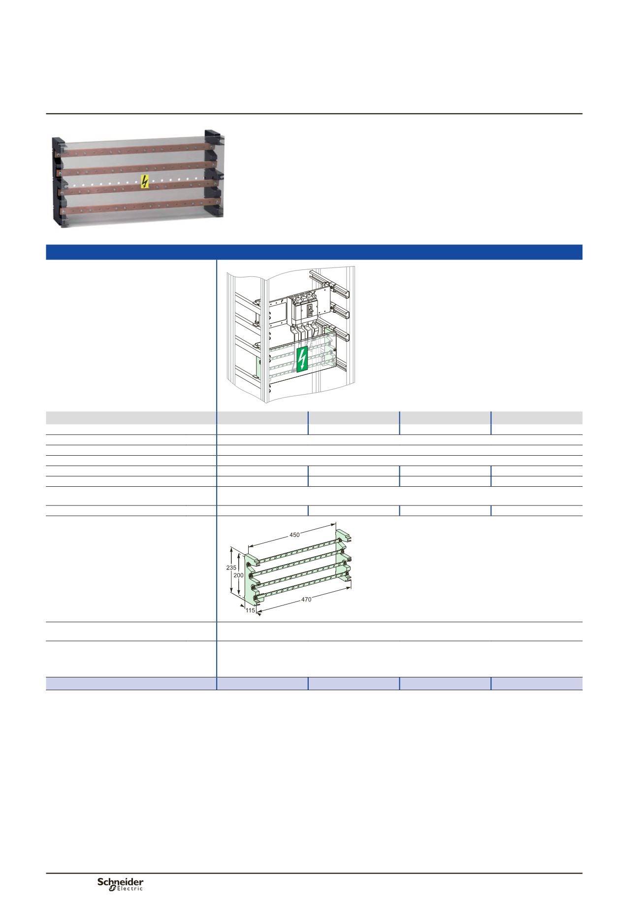
Multi-stage distribution block up to 630 A
Distribution
Power busbars
Multi-stage distribution block
Dd383647-SE.eps
160 A
250 A
400 A
630 A
Rated peak withstand current
(Ipk)
30 kÂ
30 kÂ
40 kÂ
40 kÂ
Rated insulation voltage
(Ui)
750 V AC
Rated operational voltage
(Ue)
440 V AC
Rated impulse withstand voltage
(Uimp) 8 kV
Rated short-time current
(Icw)
10 kA rms/1 s
13 kA rms/1 s
20 kA rms/1 s
25 kA rms/1 s
Thermal stress
(A².s) 1.000 x 10
8
1.690 x 10
8
4.000 x 10
8
6.250 x 10
8
Total connection capacity
4 incomers per phase: Ø12.2 mm clearance holes
13 outgoers per phase 16 to 50 mm
2
: M6 tapped holes
Busbar cross-section
15 x 5 mm
20 x 5 mm
32 x 5 mm
32 x 8 mm
Dimensions (mm)
DD381344-LIN-40.eps
Installation
Screwed onto a solid or pre-slotted plate (fixing centres 450 x 200 mm)
Screwed to an adapter cat. no.
03595
.
Composition
2 multi-stage supports made of an insulating material
4 slanted copper busbars, with holes every 25 mm
1 pack of 36 M6 x 16 screws + contact washers
1 IPxxB front insulating shield
Catalogue numbers
04052
04053
04054
04055
IEC 61439-1 & 2
Description
The distribution block can be installed horizontally in the device zone or vertically in
the 300 mm wide duct of enclosures and cubicles.
The distribution block is made up of:
b
b
two staggered supports made of an insulating material
b
b
four slanted copper bars with holes every 25 mm.
PB502514_60.eps