
B-32
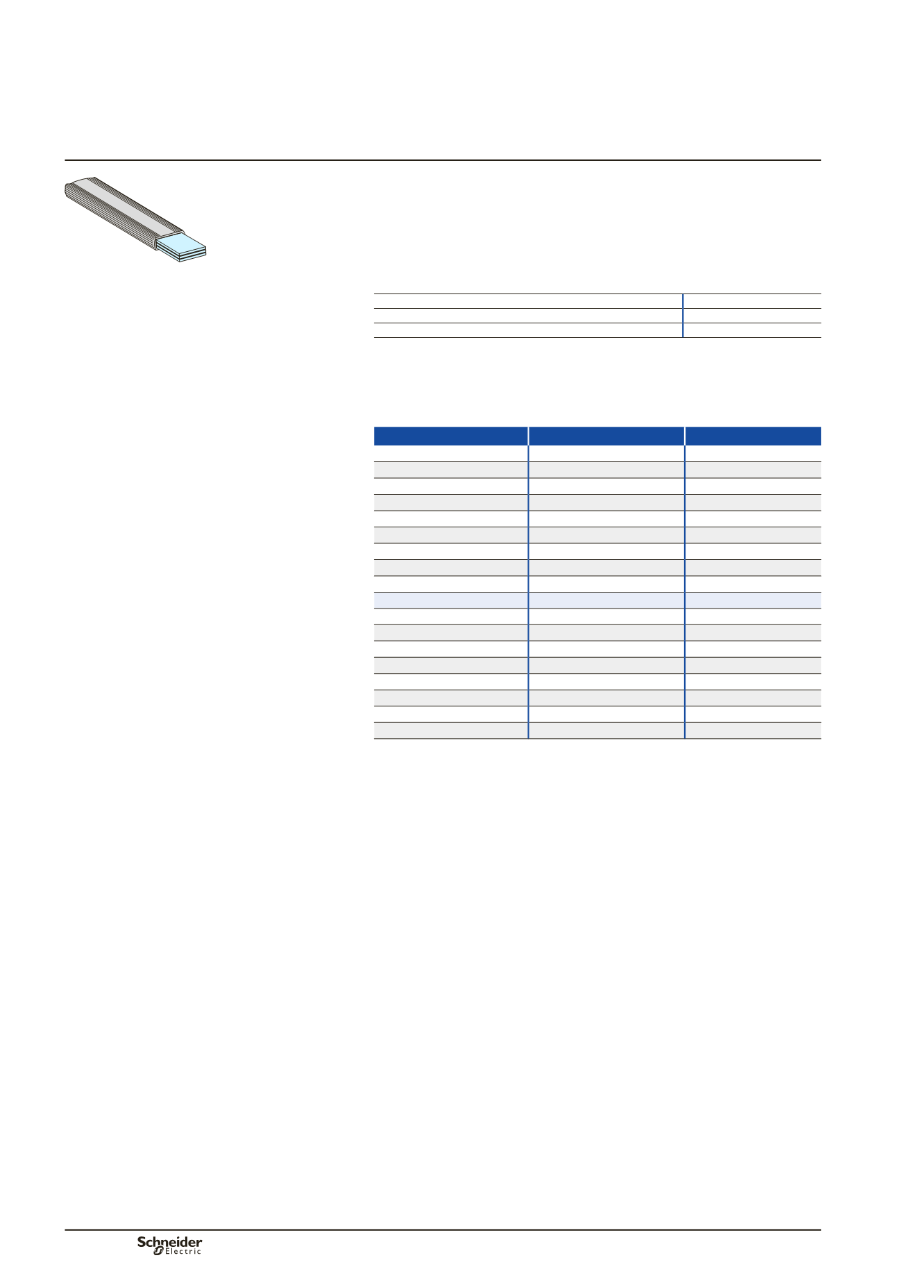
The insulated flexible bars are tested in a type-tested switchboard environment.
Their design takes into account the switchboard architecture where they are often in
close proximity to a protection device (circuit breaker or fuse) with significant heat
losses.
The sizes for the flexible bars indicated below take into account the heat losses of
Schneider Electric devices in a Prisma switchboard.
Characteristics
Width
1800 mm
Rated insulation voltage (Ui)
1000 V
Maximum withstand temperature for the insulating material
125 °C
Connection between device and busbars
The flexible bars are determined taking into account the connected device, whatever
the internal temperature of the switchboard.
The bar sizes indicated below take into account the derating curves of devices.
Devices
Size (mm)
Catalogue number
NSX100
20 x 2
04742
NSX160/250
20 x 3
(1)
04743
NSX400
32 x 5
04751
NSX630
32 x 8
(2)
04753
INS125/160
20 x 2
04742
INS250
20 x 3
04743
INS400
32 x 5
04751
INS630
32 x 6
04752
FM 200 A Linergy
20 x 3
04743
FC 3P Linergy
32 x 8
(2) (4)
04753
FC 4P Linergy
32 x 8
(2) (3) (4)
04753
Fupact 250
24 x 5
04746
Fupact 400
32 x 5
04751
Fupact 630
32 x 8
(2)
04753
Easypact CVS100
20 x 2
04742
Easypact CVS160/250
20 x 3
(1)
04743
Easypact CVS400
32 x 5
04751
Easypact CVS630
32 x 8
(2)
04753
(1)
To connect a Compact NSX250 to Linergy BW busbars, use a 24 x 5 mm flexible bar (04746).
(2)
The insulated flexible bars is not compatible with Form 2 partitioning (04922).
In this case, use the form 2 restoration kit 04924 (see page B-58).
(3)
In case of use of 32 x 6 insulated flexible bar, please contact Schneider Electric.
(4)
Max length 500 mm per connection
The references
87646
(3P) and
87647
(4P) can be used up to 250 A, when binding of
insulated flexible bars, to withstand Isc.
Insulated flexible bars
Distribution
Secondary distribution
DD381659.eps


