


 88 / 210

Linergydistributionsystems
Power busbars
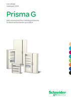
LinergyBS
Multi-stagedistributionblocks up to630A
Multi-stage distribution blocks
DD381342-LIN.eps
DD381343-LIN.eps
160 A
250 A
400 A
630 A
Rated peak withstand current
(Ipk)
30 kÂ
30 kÂ
40 kÂ
40 kÂ
Rated insulation voltage
(Ui)
750 V AC
Rated operational voltage
(Ue)
440 V AC
Rated impulse withstand voltage
(Uimp) 8 kV
Rated short-time current
(Icw)
10 kA rms/1 s
13 kA rms/1 s
20 kA rms/1 s
25 kA rms/1 s
Thermal stress
(A².s)
1.000 x 10
8
1.690 x 10
8
4.000 x 10
8
6.250 x 10
8
Total connection capacity
4 incomers per phase: Ø 12.2 mm clearance holes
13 outgoers per phase 16 to 50 mm
2
: M6 tapped holes
Busbar cross-section
15 x 5 mm
20 x 5 mm
32 x 5 mm
32 x 8 mm
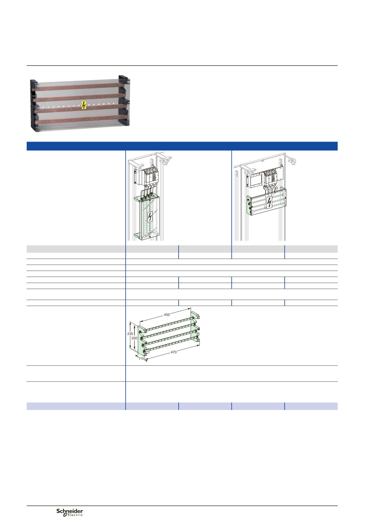
Dimensions (mm)
DD381344-LIN.eps
Installation
Screwed in horizontal position on functional uprights in enclosures and cubicles (Prisma G)
Screwed in vertical position on sheathed uprights (Prisma G)
Screwed onto a solid or pre-slotted plate (fixing centres 450 x 200 mm)
Composition
2 multi-stage supports made of an insulating material
4 slanted copper busbars, with holes every 25 mm
1 pack of 36 M6 x 16 screws + contact washers
1 IPxxB front insulating shield
Catalogue numbers
04052
04053
04054
04055
IEC 61439-1 & 2
Description
The multi-stage distribution block can be installed horizontally in the device zone or
vertically in the 300 mm wide duct of enclosures and cubicles.
The distribution block is made up of:
b
b
two staggered supports made of an insulating material
b
b
four slanted copper bars with holes every 25 mm.
PB502514_60.eps
88