


 86 / 210

Linergydistributionsystems
Power busbars
LinergyBS
Rear flat busbars up to400A
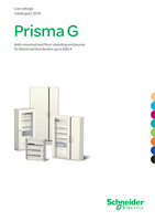
Copper busbars 160 à 400 A
DD381388-LIN.eps
160 A
250 A
400 A
Rated peak withstand current
(Ipk)
30 kÂ
40 kÂ
55 kÂ
Rated insulation voltage
(Ui)
1000 V AC
1000 V AC
1000 V AC
Rated short-time current
(Icw)
10 kA rms / 1s
13 kA rms / 1s
25 kA rms / 1s
Thermal stress
(A².s)
1.000 x 10
8
1.690 x 10
8
6.250 x 10
8
Conductor cross-section
15 x 5 mm
20 x 5 mm
32 x 5 mm
Installation
Threaded M6 holes every 25 mm all the way up
Connection by: 16 to 50 mm
2
flexible cables with crimped lugs
Set of
4
Length (mm)
1000
1400
1000
1400
1000
1400
Catalogue numbers
04161
04171
04162
04172
04163
04173
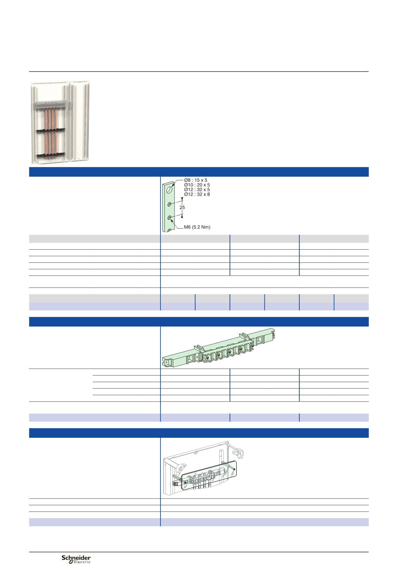
Insulating busbar support
DD381389-LIN.eps
Distance between supports
depending on Icw
(1)
y
10 kA rms / 1 s
450 mm
450 mm
450 mm
y
13 kA rms / 1 s
-
450 mm
450 mm
y
15 kA rms / 1 s
-
450 mm
450 mm
y
20 kA rms / 1 s
-
-
300 mm
y
25 kA rms / 1 s
-
-
225 mm
Installation
On the rear uprights
Screwed onto a solid or pre-slotted plate (fixing centres 450 x 200 mm)
Catalogue numbers
04191
04191
04191
IPxxB insulating protective shield
DD381192LIN.eps
Length
470 mm
Height
100 mm
Composition
Supplied with fixings
Catalogue numbers
04198
(1)
Linergy FM 200 A distribution blocks with connections ref.
04029
can act as intermediate supports (max. distance apart 200 mm) in addition to the support
ref.
04191
at the top and bottom.
IEC 61439-1 & 2
Description
The busbar can be 3-pole or 4-pole with ratings between 160 A and 400 A.
2 lengths are available: 1000 and 1400 mm, which can be cut as required.
The number of supports depends on the installation maximum rated current.
The supports allow installation of a 5th busbar with 15 or 20 x 5 mm cross-section to
create the earth collector.
PD390532_SE.eps
86