


 147 / 182

D-6
Electrical diagrams
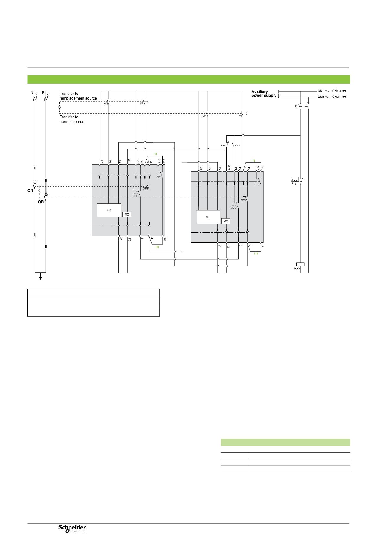
Electrical interlocking with emergency off by shunt release
DB401809
ATTENTION
(1)
Not to be wired on fixed version.
The diagram shows the electrical wiring for circuit breakers.
When wiring the SDE with
switch-disconnectors, connect
the SDE to terminals 81 and 84.
Legends
QN
“Normal” source Compact NS630b to 1600
QR
“Replacement” source Compact NS630b to 1600
OF...
breaker ON/OFF indication contact
SDE1
“fault-trip” indication contact
CE1
“connected-position” indication contact (carriage switch)
F1
auxiliary power supply circuit breaker
MX
shunt release
BP
emergency off button with latching
KA3
auxiliary relay
ON
“Normal” source opening order
OR
“Replacement” source opening order
FN
“Normal” source closing order (0.25 second delay)
FR
“Replacement” source closing order (0.25 second delay)
MT
Motor Mechanism
States permitted by mechanical interlocking system
Normal
Replacement
0
0
1
0
0
1
Note:
after a fault trip, the breaker must be reset manually by pressing
its reset button.
Diagram shown with circuit breakers in connected position, open,
charged, and ready to close.
Auxiliary power supply = supply voltage of auxiliary relays (KA...)
= supply voltage of electrical auxiliaries (electrical operation,
MCH, MX, MN...).
2 Compact NS630b/1600 devices
Diagram no. 51201181