


 145 / 182

D-4
Electrical diagrams
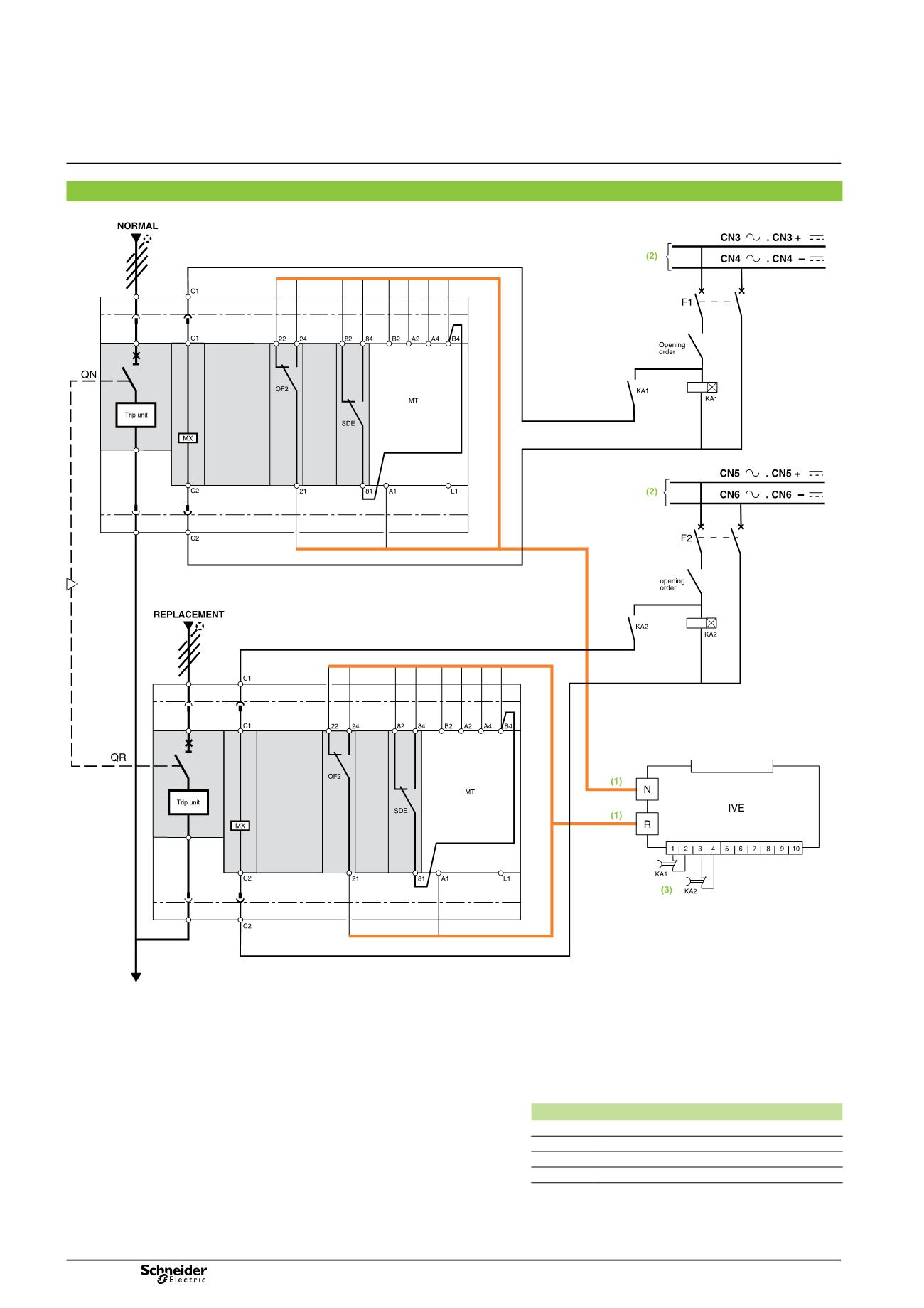
Source-changeover system without automatic-control system
With emergency off by MX release and automatic reset
DB401807
Automatic reset
(1)
Prefabricated wiring supplied
(2)
This source can be:
b
the source present in the case of voltage monitoring
b
an independent source.
In this case, the MX release must be protected.
(3)
The reset orders must be delayed by 0.3 seconds.
Legends
QN
“Normal” source Compact NSX equipped with motor
mechanism
QR
“Replacement” source Compact NSX equipped with motor
mechanism
SDE
“fault-trip” indication contact
OF2
breaker ON/OFF indication contact
MX
shunt release
MT
motor mechanism
IVE
electrical interlocking and terminal block unit
KA1
time-delayed auxiliary relays
KA2
time-delayed auxiliary relays
F1
auxiliary power supply circuit breaker
F2
auxiliary power supply circuit breaker
States permitted by mechanical interlocking system
Normal
Replacement
0
0
1
0
0
1
Note:
after a fault trip, the breaker must be reset manually by pressing
its reset button.
Diagram shown with circuits de-energised, circuit breakers open
and relays in normal position.
2 Compact NSX100/630 devices
Diagram no. 51201179