


 142 / 182

D-1
Electrical diagrams
Electrical interlocking by the IVE unit
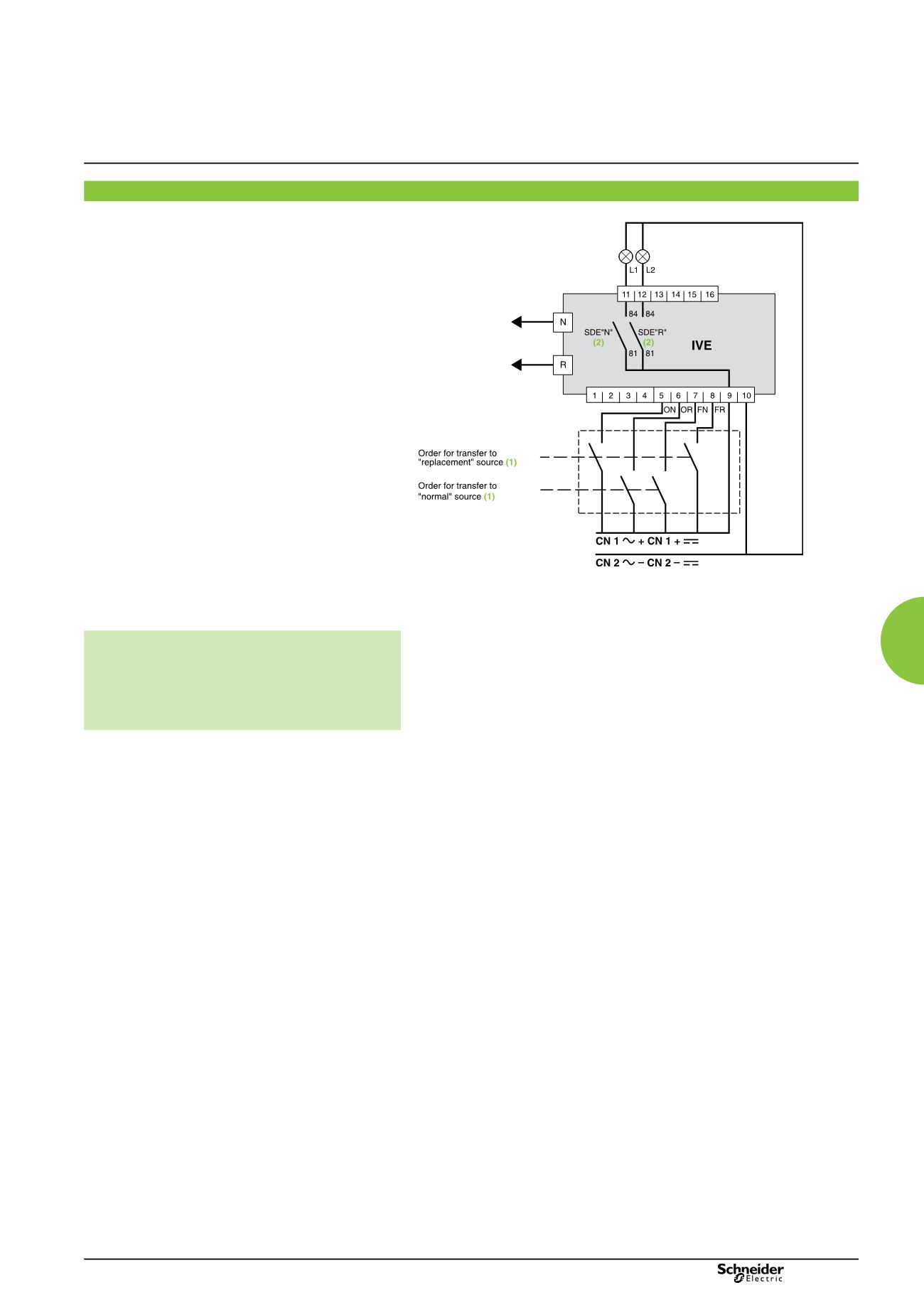
Recommended electrical control system
DB401804
(1)
See section “IMPORTANT” here after.
(2)
Operating diagram: the SDE “fault-trip” signals are transmitted to the IVE unit. The SDE
auxiliary contacts are mounted in the circuit breakers.
IMPORTANT
The relays controlling the “normal” and “replacement”
circuit breakers must be mechanically and/or
electrically interlocked to prevent them from giving
simultaneous closing commands.
Legends
ON
“Normal” source opening order
OR
“Replacement” source opening order
FN
“Normal” source closing order
FR
“Replacement” source closing order
L1
“Normal” source “fault-trip” signal
L2
“Replacement” source “fault-trip” signal
N
“Normal” source auxiliary wiring connector
R
“Replacement” source auxiliary wiring connector
Note:
diagram shown with circuits de-energised, circuit breakers open
and relays in normal position.
Remote-operated
source-changeover systems
2 Compact NSX100/630, NS630b/1600
or Masterpact NT/NW devices