


 261 / 576

261
Accessories
Power distribution
Busbar support accessories
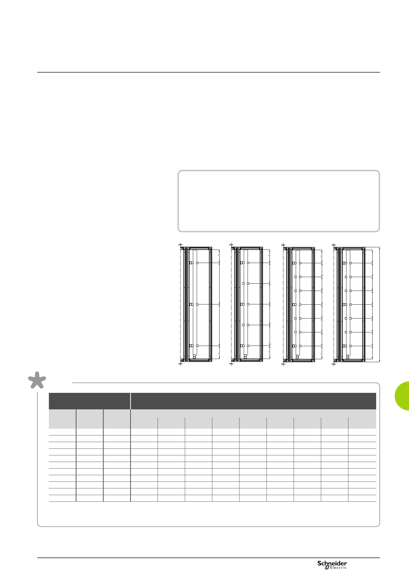
Selection of the number of supports
b
b
The number and cross-section of the bars are chosen for each phase, according
to the nominal rating.
b
b
Determine the short-circuit current Icw (kA) and use the table to obtain the
maximum distance between supports.
b
b
Based on the maximum distance between supports, obtain the number of
supports to be installed according to the following criterion:
v
v
three vertical supports must necessarily be fixed to the structure
(ref.
NSYBVS
...),
v
v
if more than three supports are required, the support arms must be used
(ref.
NSYBSA
), in even numbers (2, 4, etc.).
Table
Sets of vertical bars
Maximum distance between bar supports (mm) according
to the short-circuit current, Icw (kA)
Nominal
rating
In (A)
Cross-
section
(mm)
No. of
bars per
phase
Icw (kA)
15
25
30
40
50
60
65
75
85
750
60 x 5
1
650
325
325
217
-
-
-
-
-
900
80 x 5
1
650
325
325
217
-
-
-
-
-
1250
60 x 5
2
650
325
325
217
163
-
-
-
-
1600
80 x 5
2
650
325
325
217
217
-
-
-
-
1080
50 x 10 1
650
650
650
325
217
217
-
-
-
1250
60 x 10 1
650
650
650
325
325
217
-
-
-
1600
80 x 10 1
650
650
650
325
325
217
-
-
-
1850
50 x 10 2
650
650
325
325
325
217
217
217
-
2000
60 x 10 2
650
650
650
325
325
325
217
217
-
2500
80 x 10 2
650
650
650
325
325
325
325
217
-
2800
100 x 10 2
650
650
650
650
325
325
325
217
163
Note:
The current-carrying capacity values in the set of bars are given for an ambient temperature of 35°C around the busbar.
The nominal rating values are indicated for IP55. The maximum values (3200 A) are achieved with ambient temperatures of less than 35°C, varying
according to the configuration and position of the busbar. See enclosed table of current-carrying capacities according to temperature, page 263.
217
217
217 217 217 217 205
205
1800
650
650
325
325 325
325
217 217 217 217 217 217
217
217
217 217 217 217 205
205
1800
650
650
325
325 325
325
217 217 217 217 217 217
DB300384EN
Example
b
b
In: 2000 A, two 60 x 10 bars are required per phase.
b
b
Icw: 50 kA.
b
b
According to the table of maximum distance between supports they must
be 325 mm.
b
b
Length of the copper bars: 1800 mm.
b
b
1700/325 = 5.23, which means 6 supports, 3 fixed vertical supports
and 3 support arms + 1 extra support for the number to be even.