


 256 / 576

256
PB500919-50
PB500915-33
PB500918-40
PB500917-40
PB500916-40
SF SFX
SM
Accessories
Power distribution
Busbars andblocks
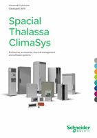
For 630 A busbars
Characteristics
630 A bar support
630 A busbar end
cover
b
b
Spacial SF:
support prepared for coupling directly to the structure of the enclosure.
b
b
Spacial SFX:
a universal cross rail is needed, in some cases, to replace the 400mm
quick-fixing cross rail.
b
b
Spacial SM:
installation by means of a vertical adaptation profile and 40 mm universal cross
rails (1 row).
b
b
Maximum nominal rating 630 A.
b
b
Determine according to the enclosed table* the cross-section of the bars and the distance
between supports, according to the nominal and short-circuit current respectively.
Busbar end protection.
Material
-
-
Fixing
-
Direct installation on the actual
bar support (insulator)
Supply
One 630 A bar support, one 40 mm quick-fixing cross rail and fixing elements
Two 630 A bar support plates
and fixing elements
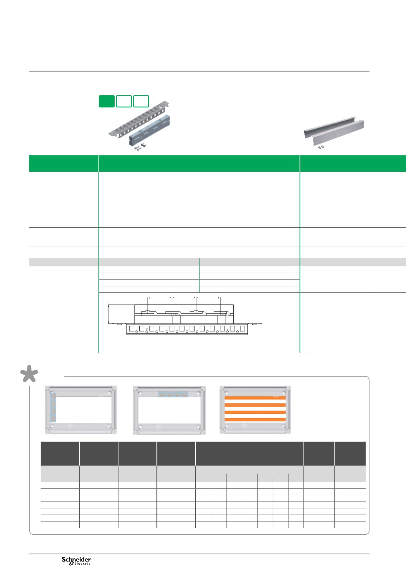
Width / Depth (mm)
References
Reference
400
NSYBS400
NSYBSC630
500
NSYBS500
600
NSYBS600
800
NSYBS800
60
60
60
47
DB300374-81
Table
Nominal
rating IP55
NR (A)
No. of
barsper
phase
Bar cross-
section
(mm)
Bar cross-
section
(mm
2
)
Maximum distance between
bar supports according to the
short-circuit current (mm)
Neutral
(mm)
Earth
(mm)
Icc kA
12 23 30 39 52 66 69
200
1
12 x 5
60
525 525 525 400 250 -
-
-
-
250
1
12 x 5
75
575 575 575 450 325 -
-
-
-
320
1
20 x 5
100
600 600 600 475 350 150 -
12 x 5-10 -
390
1
25 x 5
125
600 600 600 475 350 150 -
12 x 5-10 6 x 3
440
1
30 x 5
150
650 650 650 650 525 400 350 20 x 5-10 10 x 3
500
1
20 x 10
200
675 675 675 525 350 150 -
25 x 5-10 10 x 6
600
1
30 x 10
300
675 675 675 600 475 325 275 30 x 5-10 10 x 6