


 259 / 576

259
PD390661-40
DB123592
PD390660d-40
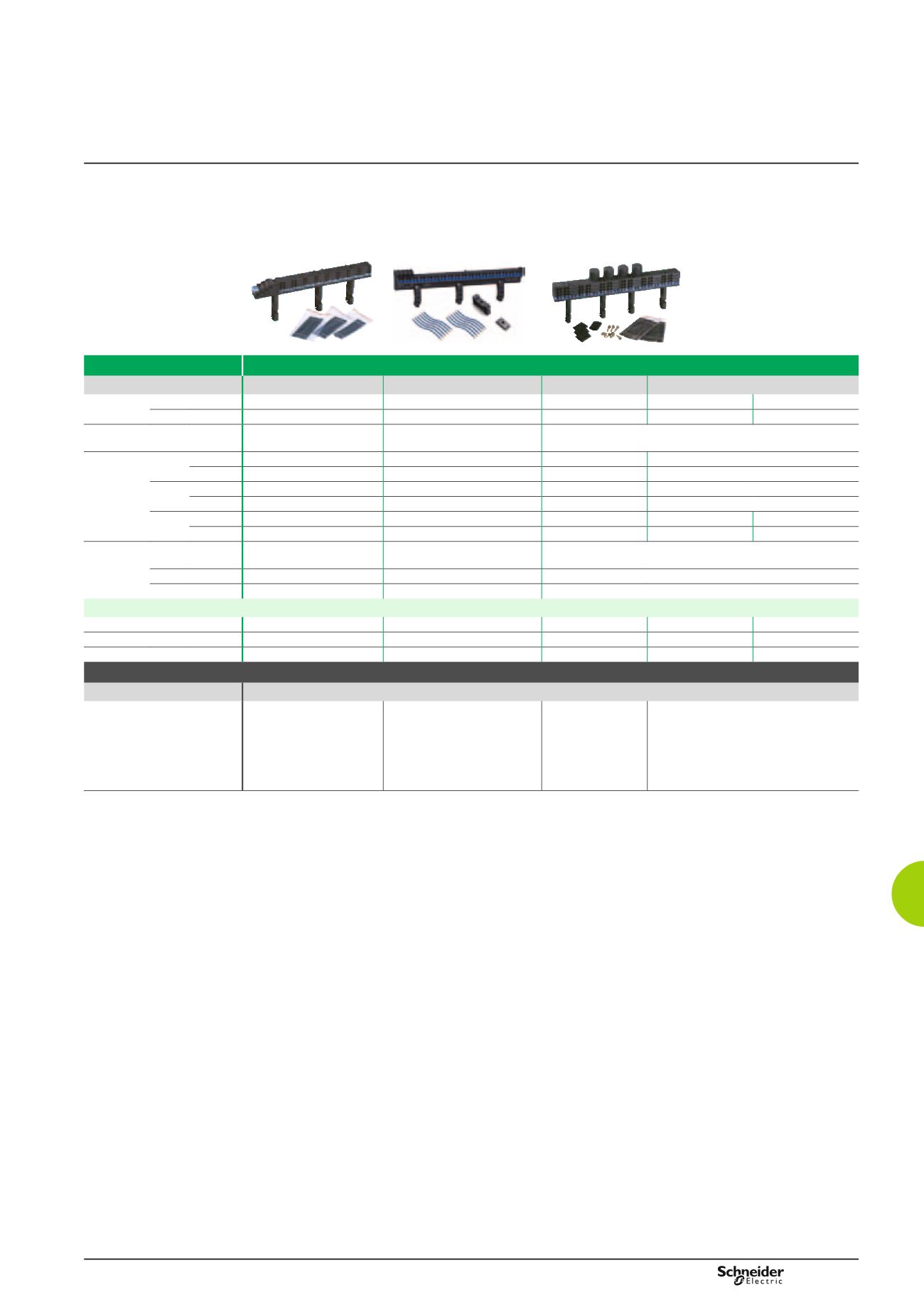
Accessories
Power distribution
Busbars andblocks
Characteristics
Linergy FM: for cable links
Rating
63 A
80 A
160 A
200 A
Length
in 9 mm modules 24
96
48
48
72
in 18 mm modules 12
48
24
24
36
Upstream connection capacity Tunnel terminals for cables
up to 25 mm²
Tunnel terminals for cables up
to 25 mm²
Direct on connecting pads by 50 mm² cables or by 20 x 3 flexible
bar with a prefabricated connection from a busbar
Downstream
connection
capacity
Max.
4 mm²
Phase 2
-
-
-
Neutral
4
-
-
-
Max.
6 mm²
Phase 2
-
-
-
Neutral
4
-
-
-
Max.
10 mm²
Phase -
18
6
12
18
Neutral
-
18
6
18
27
Accessories
included
Pre-stripped copper
connections
10 of 4 mm² + 6 of
6 mm² (L=100 mm)
12 blue + 12 black
20 of 4 mm² + 6 of 6 mm² (L=100 mm)
Protective cover
-
-
For pads (IPxxB)
Screws and nuts -
-
For pads
References
2P
-
-
-
04012
-
3P
-
-
-
04013
-
4P
04008
04000
04018
04014
04026
Accessories
Type
Manufactured cable links for upstream liaison
References / type of liaison -
-
4 x 160 A cable links
04030
- Between
Linergy FM and
switchgear
4 x 200 A cable links
04021
- Between Linergy FM and
Powerclip busbar
04029
- Between Linergy FM and
back busbar
04024
- Between Linergy FM and
busbar in duck
Linergy FM
Insulated busbars - spring connection