


 263 / 576

263
Accessories
Power distribution
Busbar support accessories
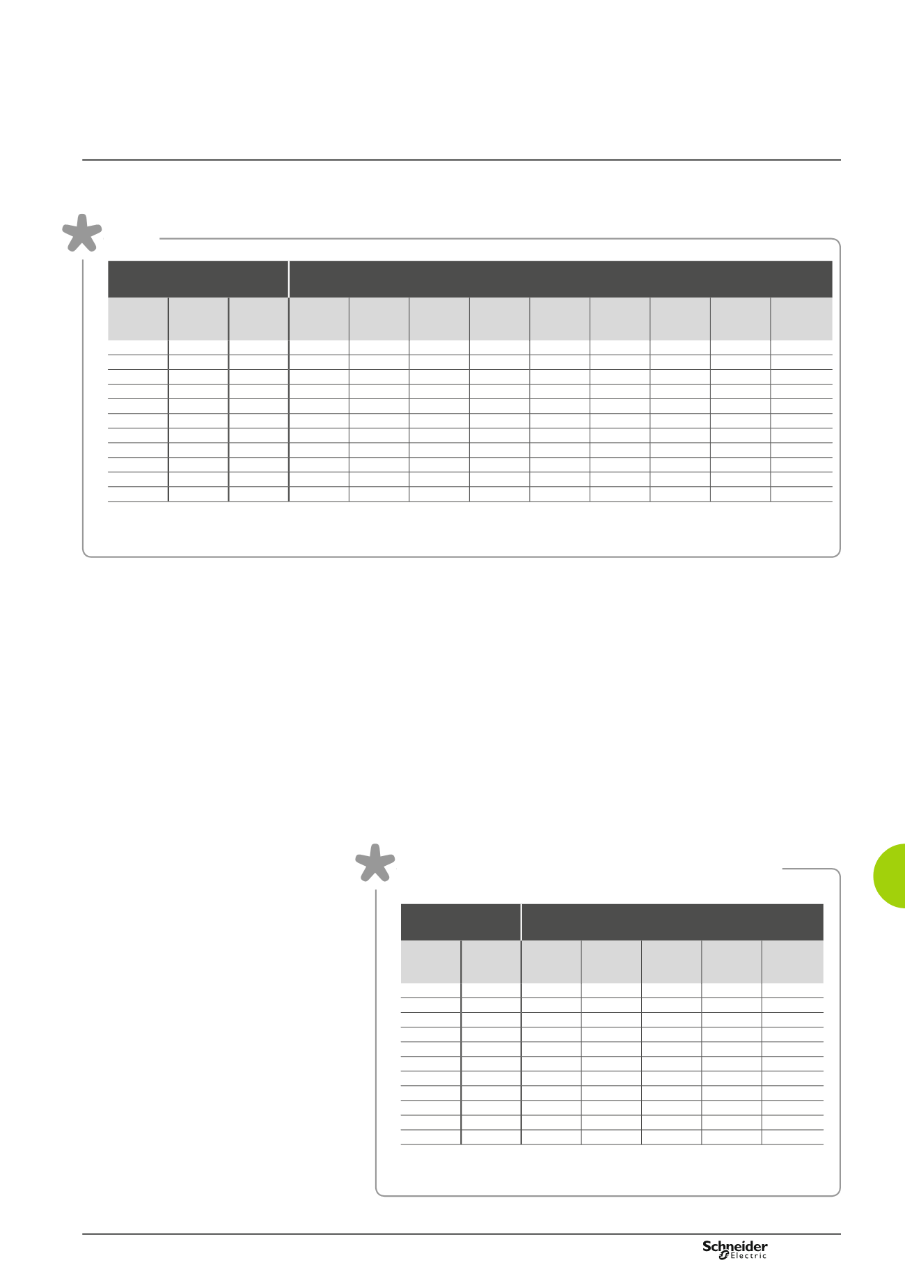
Table
Sets of vertical bars
Maximum distance between bar supports (mm) according
to the short-circuit current Icw (kA)
Nominal
rating
In (A)
Cross-
section
(mm)
No. of
bars per
phase
15
25
30
40
50
60
65
75
85
750
60 x 5
1
650
325
325
217
-
-
-
-
-
900
80 x 5
1
650
325
325
217
-
-
-
-
-
1250
60 x 5
2
650
325
325
217
163
163
130
108
81
1600
80 x 5
2
650
325
325
217
217
163
130
108
81
1080
50 x 10 1
650
650
650
325
217
217
163
-
-
1250
60 x 10 1
650
650
650
325
325
217
163
130
108
1600
80 x 10 1
650
650
650
325
325
217
163
130
108
1850
50 x 10 2
650
650
325
325
325
217
217
217
163
2000
60 x 10 2
650
650
650
325
325
325
217
217
163
2500
80 x 10 2
650
650
650
325
325
325
325
217
163
2800
100 x 10 2
650
650
650
650
325
325
325
217
163
Note:
The current-carrying capacity values in the set of bars are given for an ambient temperature of 35°C around the busbar. The nominal rating values
are indicated for IP55. The maximum values (3200 A) are achieved with ambient temperatures of less than 35°C, varying according to the configuration
and position of the busbar. See enclosed table of current-carrying capacities according to temperature.
Selection of the number of supports
b
b
The number and cross-section of the bars are chosen for each phase, according
to the nominal rating.
b
b
Determine the short-circuit current Icw (kA) and use the table to obtain the
maximum distance between supports.
b
b
Based on the maximum distance between supports, obtain the number of
supports to be installed according to the following criterion:
v
v
two supports must necessarily be fixed to the structure per enclosure. In the event
of enclosure suites, only one support is required, fixed to one of the uprights of the
coupling,
v
v
if more than two supports are required per enclosure, the support arms must be
used (ref.
NSYBSA
).
Table of current-carrying capacities according
to temperature
Type of bars
Current-carrying capacity (A) according to
the ambient temperature around the frame
Cross-
section
(mm)
No. of
bars
per phase
25°C 30°C 35°C 40°C 45°C
60 x 5
1
840
790
750
700
650
80 x 5
1
1050
990
900
870
810
60 x 5
2
1420
1350
1250
1180
1090
80 x 5
2
1820
1720
1600
1510
1390
50 x 10
1
1220
1160
1080
1010
940
60 x 10
1
1400
1320
1250
1160
1070
80 x 10
1
1800
1700
1600
1500
1390
50 x 10
2
2090
1980
1850
1740
1610
60 x 10
2
2270
2140
2000
1870
1720
80 x 10
2
2820
2660
2500
2330
2160
100 x 10 2
3200
3100
2800
2720
2510
Note:
The rating values according to temperature are not exhaustive, since they depend on
the configuration and position of the bars inside the enclosure.