


 257 / 576

257
PB500921-44
DB300375-38
PB500920-37
Accessories
Power distribution
Busbars andblocks
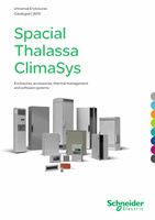
630 Amulti-stage bar support
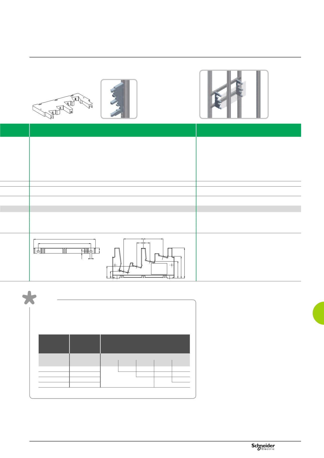
Screen for 630 Amulti-stage busbar
b
b
Support for fixing bars with cross-sections: 15 x 5, 20 x 5, 32 x 5, 32 x 8.
b
b
The orientation of the copper bars makes tightening easier and allows better circulation of the
cables.
b
b
It can be 3-pole or 4-pole, with gauges from 160 to 630 A.
b
b
Electrical characteristics:
v
v
Rated peak withstand current Ipk (kÂ):
- 30 k for 160 A busbar,
- 40 k for 250 A busbar,
- 55 k for 400 A and 630 A busbar.
v
v
Rated insulation voltage Ui = 750 V.
b
b
Protects against direct contact from the front in the
connections of the busbar.
b
b
Length: 1500 mm.
Insulating plastic
-
b
b
Mounting on mounting plates (see page 220) or cross-rails (see page 232)
b
b
M6 x 25 self-tapping screws are required for fixing on the cross-rails, not included
Direct mounting on the actual support
1 multi-stage bar support and fixing elements
1 screen for multi-stage busbar and fixing elements
Reference
Reference
04192
04197
200
235
7
8.5
20
75
75
25 25
45
26
64
83
115
200
235
7
8.5
20
75
75
25 25
45
26
64
83
115
DB300376EN-52
Table
Rating
(A)
Bar cross-
section
(mm)
Centre-to-centre distance of the
supports (mm)
Icw (kA eff/1 s)
10
13
15
20
25
160
15 x 5
250
20 x 5
450
400
32 x 5
300
300
(1)
630
32 x 8
(1) Icw (kA eff/0.6 s).
The following table shows:
b
b
The cross-section of the bars that will be used according to the current-carrying
capacity in the busbar.
b
b
The distance between the bar supports that will be installed according to the
rated short-time withstand current: Icw.