


 255 / 327

TECHNICAL INFORMATION
Technical information
Wire Basket
| 255
18
The distance between supports is of 1.2 m and
the maximum load is of 10 kg/m.
The systemmay have one or two levels.
Earth bonding
For earth bonding requirements please refer to
the currentWiring Regulations BS7671 and all
current amendments.
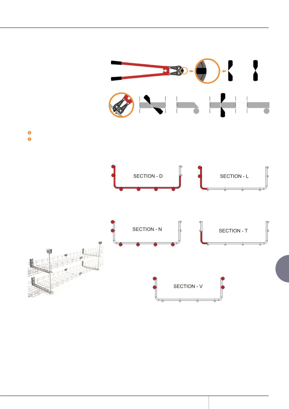
Cutting
Always use asymmetrical cut wire cutters. Cut as close as you can to where horizontal and vertical
rods cross each other, as shown.
We recommend always placing the basket on a flat surface to make the cuts.
The below drawings show in red the section cuts that are needed for the bends, tees and
changing levels as explained in the Installation section on pages 97-99.
EMC and Data
It is recommended to separate power and
data circuits by a minimum of 20cm.
(EN 50174-2)
Where power and data circuits must cross, this
must be done at 90 degrees.
Wire Basket systems without electrical
continuity do not protect against
electromagnetic fields. Make sure electrical
continuity is preserved by using the
appropriate earth bonding accessories.
Electrical continuity
Our Fast-CouplingWire Basket conforms to IEC
61537. The wire mesh basket has an
impedance lower than:
50mΩ across the joint
5mΩ per metre in a straight section
Fire Resistance
Marshall-Tuex and Basor Electric certifies
that the wire basket installed with the
below mentioned characteristics complies
with Class E90 of functionmaintenances, in
accordance with Standard DIN 4102, Section
12.
This system incorporates StandardWire Basket
with a height of 65mm. This system uses Fast
FixWall Bracket supports fixed to the wall and
reinforced on the ceiling using the Variable
Support Bracket, M8 Threaded Rod and M8
Nut on one side, as per the below image.
45
o
OK
NO
OK
NO