


 250 / 327

Tel
+44 (0)1424 856600
Fax
+44 (0)1424 856611
Technical Hotline
+44 (0)1424 856688
TECHNICAL INFORMATION
Technical information
250 |
GRP ladder and tray
Load characteristics
Coefficient of safety > 1.7 (in accordance with IEC 61537) this data is
given for ladders coupled with splice plates and bolts.
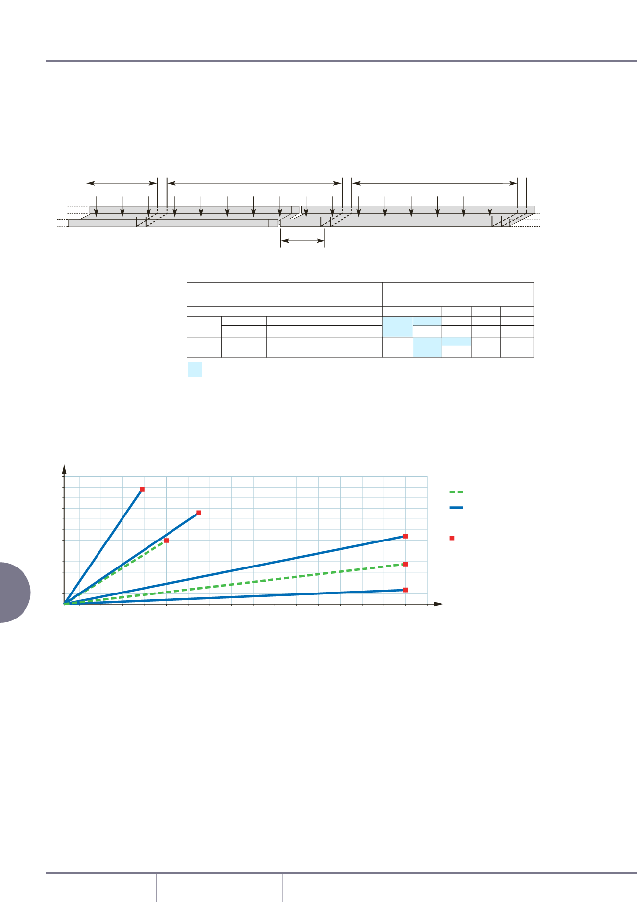
The deflection values are
measured with the position of
the junction between 2 ladders at
a distance L/5 from a support. If
this distance is not respected, it is
necessary to raise the deflection
values by about 30% when fully
loaded.
Series UL load diagram: supporting distances from 2 to 5m.
For 100mm and 150mm wall height refer to Marshall-Tufflex.
Localised loads
To be able to compare this to a uniformly distributed load it is necessary
to double the value of the localised load. Example: A 60kg local load at
the centre of a ladder with 3m of support distance. Equivalent load: 60 x
2 = 120kg uniformly distributed along 3m (ie 40kg/m).
L
0,4 L
L/5
L= support distance 1500mm
L
Deflection (mm)
uniformly distributed
load Kg/m
60
50
40
30
20
10
20
40
60
80
100
120
140
160
0
5 m
2 m
2 m
3 m
3 m
4 m
UL 53
UL 80
acceptable load
limit
(above these loads,
please consult
Marshall-Tufflex)
Optimalconditions,forcostreductiononyour installation.
Usefularea
Weightof
Maximumadmissable loadkg/m
(mm
2
)
cableskg/m accordingtothedistancebetweensupports
2m 3m 4m 5m 6m
UL…53
05
052 = 0259 – 0244 003 – 051
400–600 12920–19720 = 550
60
50
UL…80
03
06
054 =04861 – 0967 003 – 051
400–600 22940–35140 = 1000
160 160
60
30
160
GRP ladder and tray - continued
Standard span pressed tray