


 249 / 327

TECHNICAL INFORMATION
Technical information
GRP ladder and tray
| 249
3
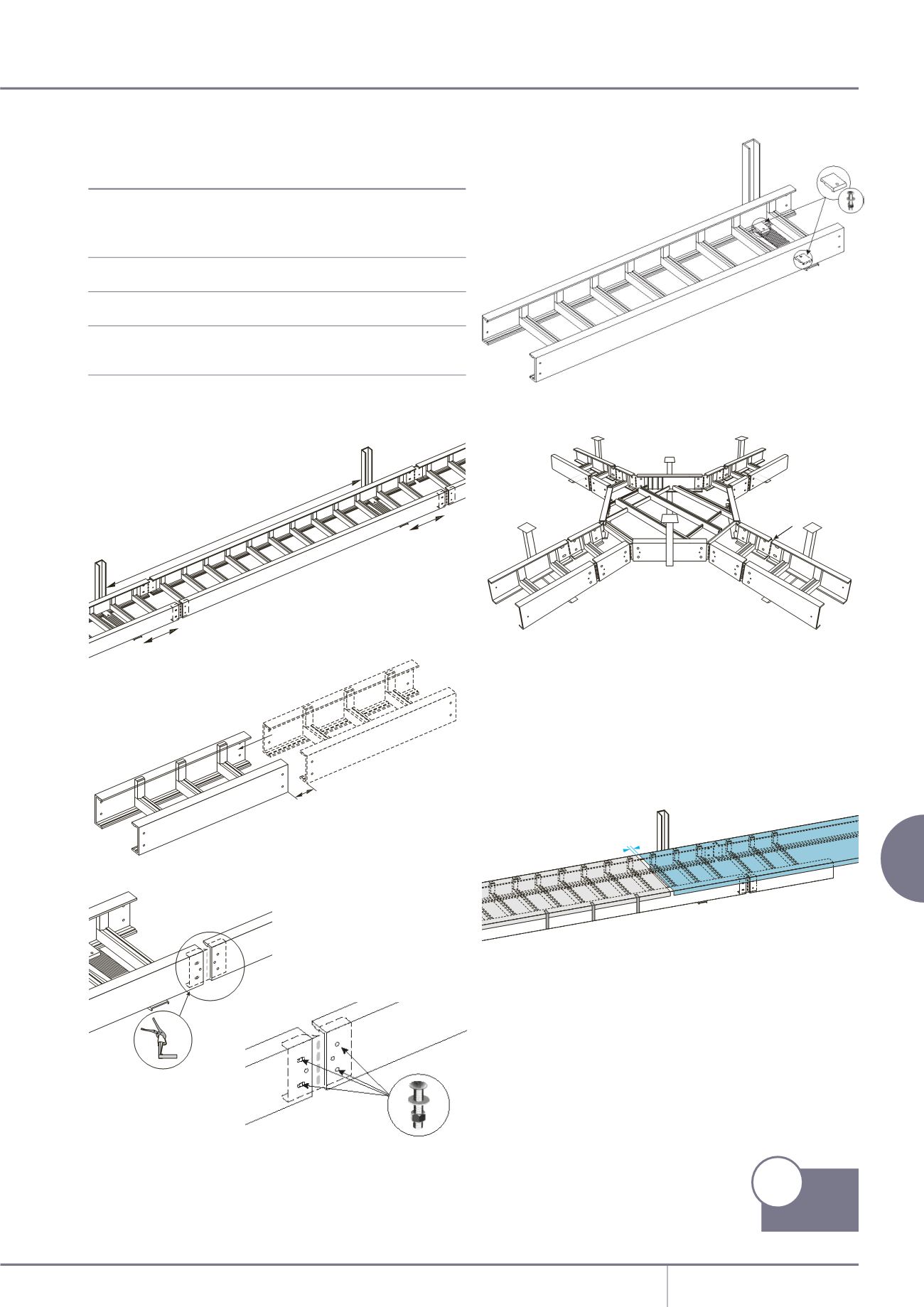
Fix the ladder at each support with
2 hold-down clamps UL KS and 2
M1030/V4A bolts.
4
Follow the installation procedure.
A All fittings must be supported at every cable entry.
B Add a central support for all fittings with radius greater than 250mm
and/or with width greater than 400mm.
C Lock systematically each splice plate UL IH with 4 M620/V4AS bolts
on fittings extremities.
5
Fix the cover with clips made of stainless steel 316 (ref.DF50, DF80,
DF100 and DF150).
Under normal conditions use 3 clips alternatively on each side per 3
metres of ladders.
Under extreme conditions (strong winds > 60km/h) use 7 clips per 3
metres of ladders.
GRP cable ladders pultruded
Resin types (all zero halogen)
Polyester (standard)
good all round performance,
mechanical strength, corrosion
resistance, fire behaviour,
temperature rating
Acrylic (on request)
excellent resistance to fire in a
corrosive environment
Vymilester (on request)
highly resistant to a specific range
of chemical agents (H2SO4HC1…)
Carbon loaded polyester
anitistaticpropertiesforhighly
(on request)
explosiveatmospheres
Alternatively for specific projects we will define a solution to meet
your needs.
A
B
C
8mm
L/5
L/5
L
30mm
1
Place the end of the ladder
about L/5 away from the
supporting bracket.
L/5 corresponds to the ideal
place for mechanical stability:
place the junction between
2 ladders at this point.
2
Connect the ladders together.
Place the side-rails facing each
other.
Fix the stainless steel splice plates
UL IH with the help of stall clips,
the oval holes* placed nearest the
supporting bracket.
Lock the junction with 4 x M620/V4AS bolts.
(*) The splice plates UL IH are pre-punched with 2 holes Ø 8mm and 2 oval
holes 20 x 8mm in order to assure a solid fixing and to allow the expansion
of the GRP material.
GRP ladder and tray - continued
Installation
p51
Product
Information