


 118 / 132

118
®
Cable tray systems are intended for the support of a combination
of cables, electrical equipment and/or communication system
installations. Where necessary cable tray systems may be used
for the segregation of cables.
Note : these systems are designed for use as supports for cables
and not as enclosures giving full mechanical protection.
These systems are covered by BS EN 61537.
1
Design factors to consider
Consideration should be given to the following factors when
undertaking the design of a support system although some
of these (e.g. snow/wind loads) may not be relevant to every
installation.
(i) Distributed loads (eg. cables, pipes)
(ii) Point loads
(iii) Snow, wind and external forces
(iv) Safety factor
(v) Deflection
(vi) Spacing of supports
(vii) Location of couplers
(viii) Testing of cables within a support system
(ix) Electrical continuity
(x) Earth protection
(xi) Electromagnetic compatibility (EMC)
The following sections provide a wealth of useful information on
each of these design aspects.
(i) Distributed loads
Before commencing the design process for a new installation
it is usual to consider whether future changes in the pattern
of demand for building services will impose increased loading
requirements on the support system. If so, it is good design
practice to allow both the physical space and sufficient load
carrying capacity for the future addition of 25% more cables or
other loading medium.
Estimation of cable loads
If full details of the cabling layout are available then the likely
cable load can be calculated using either manufacturer’s
published information or the tables of cable weights and
diameters which are given opposite. However, it is often necessary
to select a tray design in the absence of accurate information
on the likely cable load. To assist this selection process a useful
approach can be to choose a likely size of tray and then to
estimate the maximum cable weight which is capable of being
contained within it. This estimate may be arrived at using the
following guide :
Steel wire cable tray systems
IN THIS SECTION...
Steel wire cable tray
systems
1. Design factors to consider
2. Loadings
Installation of
services
Table 1 : PVC armoured power/control cables to BS 6346
Nom. area
2 core
3 core
4 core
of conductor
(mm
2
)
kg/m D in mm
kg/m D in mm
kg/m D in mm
1·5
0·3
12·3
0·3
12·8
0·4
13·5
2·5
0·4
13·6
0·4
14·1
0·5
15·0
4·0
0·5
15·1
0·5
15·8
0·7
17·8
6·0
0·6
16·5
0·7
18·0
0·9
19·2
10·0
0·9
20·1
1·0
21·2
1·2
22·8
16·0
1·0
21·9
1·2
23·1
1·7
26·3
Table 2 : PVC insulated and sheathed circular surface wiring
Nom. area
2 core
3 core
4 core
of conductor
(mm
2
)
kg/m D in mm
kg/m D in mm
kg/m D in mm
1·5
0·1
7·7
0·1
8·2
0·1
9·1
2·5
0·1
9·2
0·2
9·7
0·2
10·6
4·0
0·2
10·2
0·3
11·0
0·3
12·6
6·0
0·2
12·0
0·3
12·8
0·4
14·2
10·0
0·4
14·6
0·5
15·6
0·7
17·4
16·0
0·6
16·9
0·7
18·0
0·9
20·0
Note :
this formula only provides an estimate of the maximum
load which can be physically contained within a tray. The ability of
that tray to support such a load depends upon the spacing of its
supports.
Cable weights and diameters
Tables 1 and 2 below give typical weights and diameters (D) for
PVC sheathed, steel wire armoured cables with stranded copper
conductors.
Tables 3 and 4 give typical weights and diameters for PVC
sheathed, unarmoured stranded copper power cables. Cables with
XLPE (cross linked polyethylene) insulation are usually slightly
lighter so the information given may also be used for these cables
too.
Values show approx. weight and diameter of typical cables.
D = Overall cable diameter.
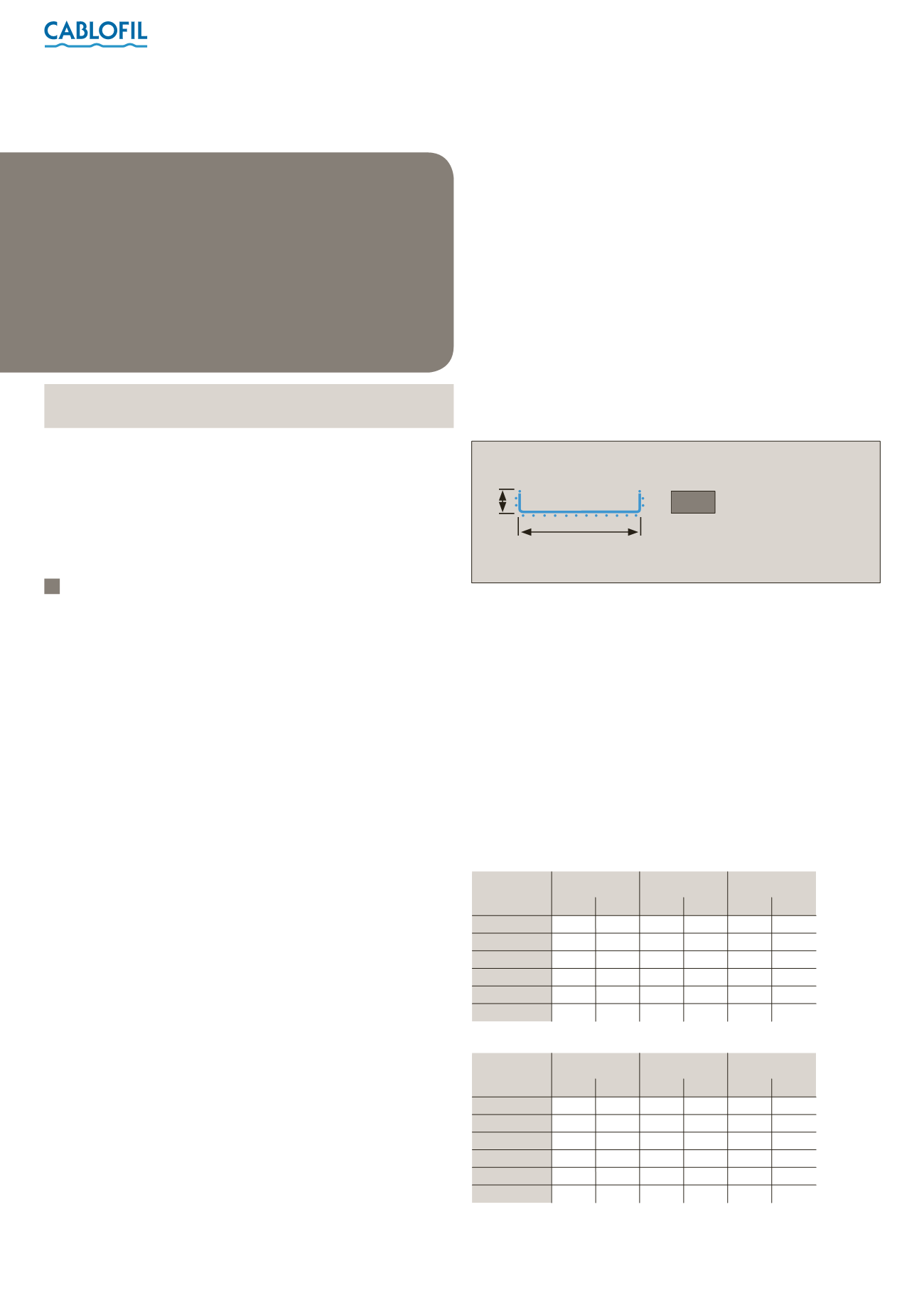
Max. cabling capacity (kg/m) = cable laying area (m
2
) x 2800
Cable laying area (m
2
) = W (m) x H (m)
Applicable to cable tray
W
H
Cable laying area