


 123 / 132

123
Reliability and durability
The two major considerations for the network infrastructures are
the reliability and durability of the installation. In order to measure
the positive contribution made by Cablofil steel wire cable tray,
even when overloaded with cables, a series of independent tests
were carried out.
• Independent tests
The aim was to develop a detailed understanding of the short-
term or long-term benefits of using Cablofil steel wire cable
tray, as opposed to conventional flat-bottomed supports, for Cat.
5e and Cat. 6 cables. Cablofil steel wire cable tray lengths were
tested by Intertek Testing Services, a division of ETL, the world’s
leading provider of testing, inspection and certification services.
• Measurements
For the two tests described below, parameters relating to cable
characteristics (NEXT, FEXT, Attenuation Return Loss, etc.)
are measured in different configurations. The main parameter
selected for comparison purposes is Return Loss. The aim is to
define a cable’s impedance regularity. Each irregularity causes
the signal to return to its source.
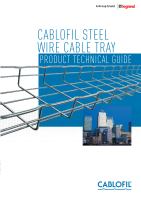
• Test 1 : reliability under load
90 metres of Cat. 5e and Cat. 6 cables were tested with no load,
before being subjected to mechanical stress equivalent to the
weight of 40 cables stacked together. Measuring and comparing
the Return Loss for each configuration determines the effect of
the support.
Results :
The tests show that, for a Category 5e or Category 6 cable
subjected to a load of 40 cables, there is no significant difference
in behaviour between Cablofil steel wire cable tray and a support
with a flat base.
Cablofil steel wire cable
tray not loaded
Cablofil steel wire cable
tray under load
Flat surface not loaded
Flat surface under load
Test configuration
<
1
m
Ω
• Test 2 : durability under load
In order to establish how data cable installations change over
time, the equipment is subjected to a simulated 15 year ageing
process based on extremely stringent military standards and the
same tests are performed. The cables and supports undergo 200
cycles over large temperature variations (-40°C to +85°C) over a
period of 2 weeks.
Results :
The cable supported by Cablofil steel wire cable tray, an open
and ventilated system, performs better than a cable laid directly
on the floor.
(ix) Electrical continuity
Fundamental to providing safety to people and property,
electrical continuity also plays an essential role in the EMC
performance of an electrical installation.
Definition
The electrical continuity of a system is its ability to conduct
electric current. Each system is characterised by its
resistance (R).
If R = 0
Ω
, the system is a perfect conductor.
If R is infinite, the system is a perfect insulator.
The lower the system’s resistance, the better its electrical
continuity will be.
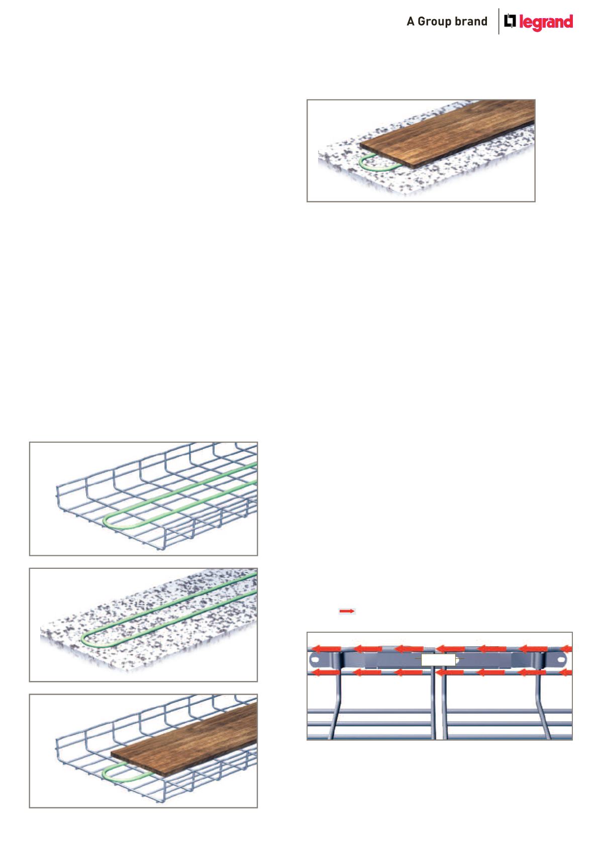
The importance of excellent electrical continuity
Even at the same electrical potential each part of the steel wire
cable tray run helps dissipate any fault currents :
Tested for electrical continuity
•
Steel wire cable tray lengths
Tests show that Cablofil steel wire cable tray lengths more
than meet the requirements of the standard IEC 61537, which
stipulates that cable tray resistance must not exceed 5 m
Ω
/m.
•
Steel wire cable tray couplers
The standard IEC 61537 states that coupler resistance must not
exceed 50 m
Ω
. The test involves running an electric
current through the system (lengths + couplers) and
measuring coupler resistance.
Test results
An average of 0·82 m
Ω
for Cablofil couplers. This is between 50
and 80 times better than the requirements given in the standard.
All Cablofil couplers are tested and compliant.
Please contact our technical support team on +44 (0)845 605
5334 for the full results of these tests.