


 124 / 132

124
®
(x) Earth protection
Earthing an installation is vital for the safety of people and
property. Furthermore it plays an active role in EMC.
Definition
The earth network is made up of all the metallic components of a
building that are interconnected. These include beams, conduits,
cable management, the metal frames or devices. All such
elements must be interconnected to ensure the earth network is
equipotential.
Benefits of equipotential earthing network
The equipotential earth network works like a system of conduits
evacuating any fault currents and the parasite currents to earth.
This provides a means of :
• protecting people and property
• obtaining a satisfactory EMC performance level
Integrating steel wire cable tray into the earth network
In order to benefit from the advantages in terms of safety and
EMC, metallic cable trays must be connected to the earth network
every 15 m.
Where tray runs are shorter than 15 m, the ends of each metal
cable tray must be connected to earth.
Any electrical circuit thus formed by the cable tray must be closed
to help remove any fault or noise currents which may arise.
Role of the protective conductor :
The protective conductor
provides a simple and effective means of connecting the cable tray
to earth.
(xi) Electromagnetic compatibility (EMC)
Understanding EMC involves the analysis of electromagnetic
pollution between a source of disturbance and its victim.
Definition
Electromagnetic interference is emitted by a source polluting a
victim. Electromagnetic interference is transmitted by a process
known as coupling. An EMC problem only occurs when the three
elements source, coupling and victim are evident. To obtain a good
EMC we simply need to eliminate one of the three elements or
reduce its effect.
Metallic cable trays with excellent electrical continuity, which are
integrated into an installation’s equipotential earthing network,
reduce the effects of coupling and therefore improve an electrical
installation’s EMC.
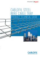
The solution offered by Cablofil steel wire cable tray
• Its open structure makes it easy to ensure correct separation by
visual inspection
• Its easy installation and metal structure guarantee excellent
electrical continuity in all cases : couplings, bends, changes of
level, crossovers etc.
• Its open structure can reduce ‘cross talk’
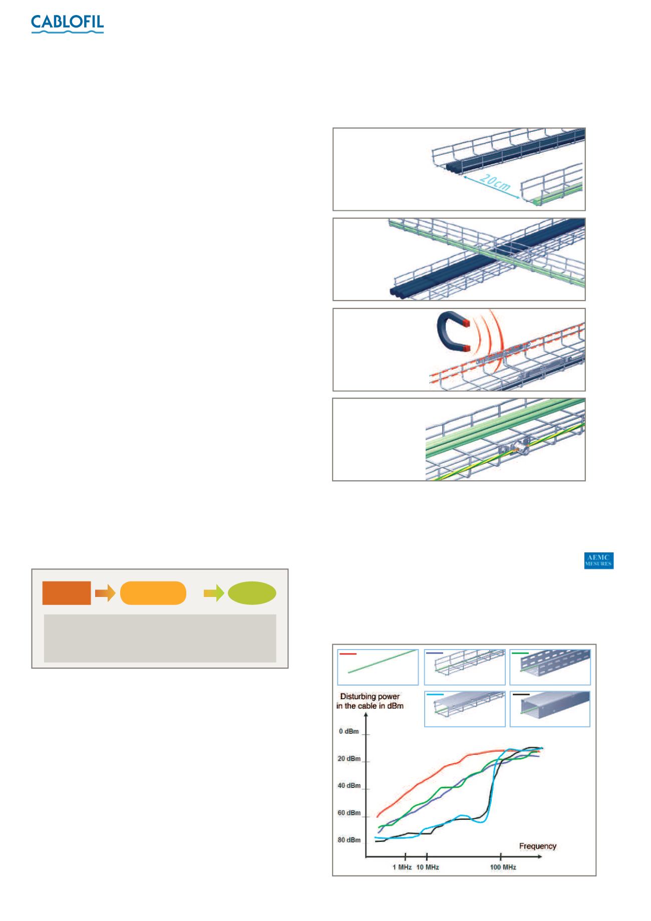
EMC tests
Tests conducted by the accredited and independent AEMC
Measures and CETIM laboratories demonstrate the performance
of Cablofil steel wire cable tray in relation to the EMC of the
electrical installation.
The golden rules!
1 :
The EN 50174-2 standard specifies how far cables must be kept apart. This
depends on the type of data cable, the number of power cables and the type of
cable tray. Otherwise, the distance of 20 cm provides a simple and sensible rule of
thumb. For precise details, please contact our technical support team on
+44 (0) 845 605 5334.
• Test 1 - configuration:
Data cable in an external electromagnetic field
A data cable (Category 5e UTP) is placed in an insulated anechoic
chamber and subjected to a powerful artificially-generated
electromagnetic field in order to simulate electromagnetic
interference.
Each tray is connected to earth and subjected to the test :
Source
Coupling
Victim
Sources include
– frequency modulators, mobile phones,
lightning, power cables, etc.
Victims include
– IT systems, devices, data cables, etc.
Make sure electrical
continuity is preserved :
use metal cable tray and
couplers.
Connect cable trays to
the earthing network
(every 15-20 m).
Make sure
different cable types
cross at right angles.
Remember the
importance of keeping
power and data cables
separate.
1
(EN 50174-2 standard)
Cable with no
metal tray (for comparison)
Cable in wire tray
Cable in perforated tray
Cable in
wire tray with cover
Cable in raceway with cover