
SCP
super compact busbar
technical information
90
n
Harmonics
In a distribution system, currents and voltages should have a perfectly
sinusoidal shape. However, in practice the equipment contains electric
devices such as changeover devices or dimmers that make the load
not linear
The currents absorbed, although at regular intervals and with
frequencies equal to that of the rated voltage, sometimes have a
non-sinusoidal wave form, which has the following negative effects :
•worsening of the power factor
•heating of the neutral
•additional losses in electric machinery (transformers and motors)
•instable operation of the protection elements (thermal magnetic and
earth leakage circuit breakers)
In industrial plants these conditions have been occurring for a long
time. However, they are now occurring more and more in service sector
distribution systems, where, from backbone distribution (which uses
3 phase lines), single phase loads are often distributed, which
contributes to increasing the unbalance of the electric system
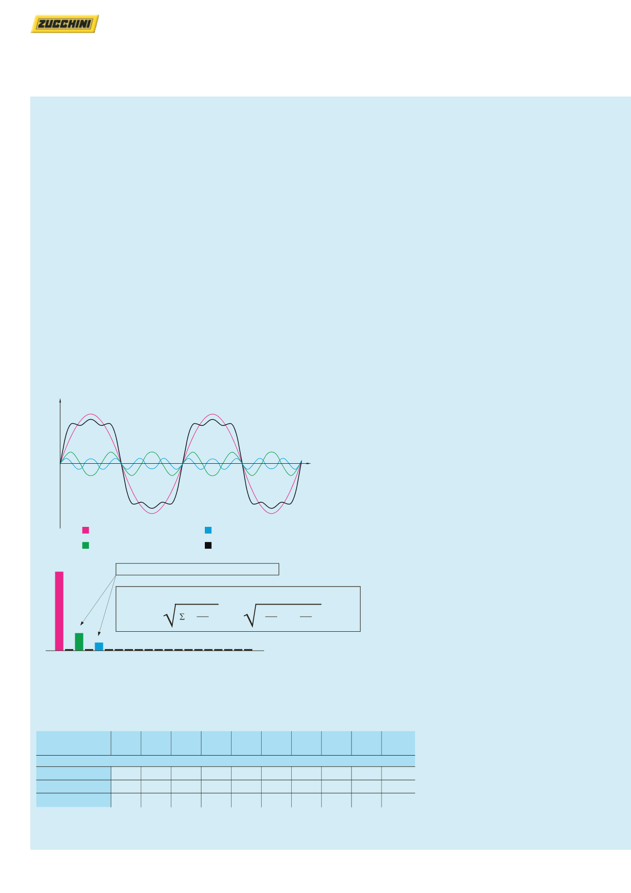
Each type of non-sinusoidal periodical wave may be split into a more or
less large number of sinusoids (called harmonic components)
A deformed current at a frequency of 50 Hz, like the example
represented by the magenta line on the figure, consists of many
sinusoidal currents with frequency of 50 Hz (fundamental), 100 Hz
(second harmonic component), 150 Hz (third harmonic), and so on
The presence of current harmonics represents an important problem,
causing overload conditions both on phase conductors, and on any
neutral conductor, and results in the reduction of the conductor’s
permitted load
Note
200% neutral versions are available for systems with harmonics present on the neutral
Choice of rating when in the presence of harmonics
When in the presence of harmonics, and when using the chosen Int
rated current, the SCP busbar to be used shall have the rating specified
in the table below
u
t
Fundamental (50 Hz)
Third harmonic (150 Hz)
Fifth harmonic (250 Hz)
Resulting wave shape
100%
23%
11%
50 100 200 300 350 400 450 500 550 600 650 700 750 800 850 900 950 1000
250
150
Hz
THD% = 100
H
h = 2
U
h
U
1
( )
2
23
100
( )
2
+
11
100
( )
2
= 100
= 25.5 %
Total distortion (THD) = 25.5%
Distortion of the individual harmonics
Measurement of harmonic distortion
carried out with a network analyser
Rated
current (A)
630 A 800 A 1000 A 1250 A 1600 A 2000 A 2500 A 3200 A 4000 A 5000 A
SCP busbar to be used
THD
≤
15%
630
800 1 000 1 250 1 600 2 000 2 500 3 200 4 000 5 000
15% < THD
≤
33%
800 1 000 1 250 1 600 2 000 2 500 3 200 4 000 5 000
–
THD > 33%
1 000 1 250 1 600 2 000 2 500 3 200 4 000 5 000
–
–


