
SCP
super compact busbar
technical information
88
n
Selection of the busbar trunking system based
on voltage drop
If the line is particularly long (> 100 m), it will be necessary to check the
value of the voltage drop. For systems with power factor (cos
j
m) not
lower than 0·8 the voltage loss can be calculated using the following
formulas :
Three phase system
Single phase system
The percentage voltage drop can be obtained from :
Where Vr is the system rated voltage
In order to limit the voltage drop in very long busbar trunking systems, it
is possible to allow for a power supply at an intermediate position, rather
than at the terminal point
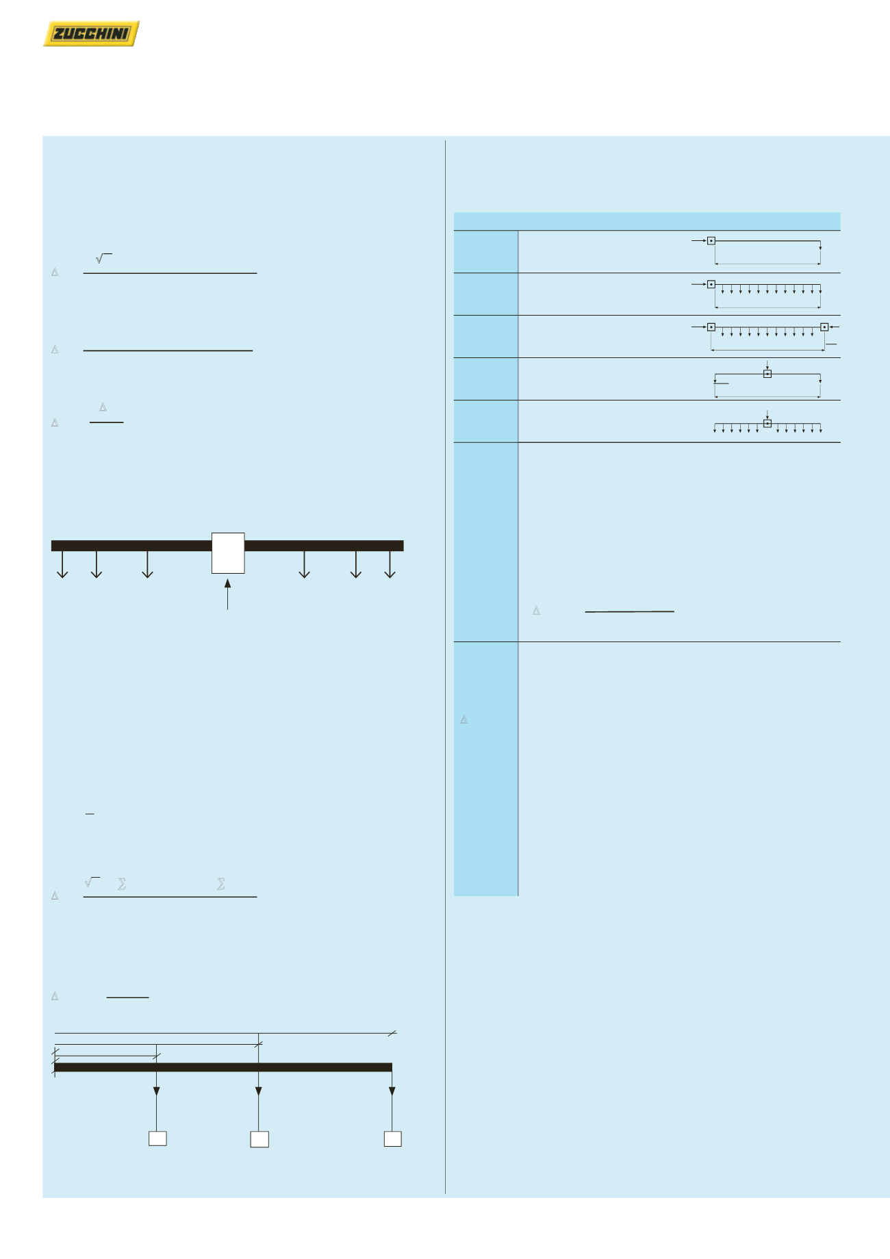
Calculation of the voltage drop with loads not
evenly distributed (continued)
The current distribution factor ‘b’ depends on how the circuit is fed and
on the distribution of the electric loads along the busbar
b
•
√
3
•
I
b
•
L
•
(R
t
•
cos
j
m + x
•
sin
j
m)
∆
v =
1000
b
•
2
•
I
b
•
L
•
(R
t
•
cos
j
m + x
•
sin
j
m)
∆
v =
1000
∆
v
∆
v% =
•
100
Vr
Loads
Loads
Busbar
trunking system
intermediate power
supply point
Calculation of the voltage drop with loads not
evenly distributed
If the load cannot be considered evenly distributed, the voltage drop
may be determined more accurately using the relationships shown
below
For the distribution of three phase loads, the voltage drop is calculated
using the following formula, on the assumption (generally verified) that
the section of busbar trunking is consistent :
∆
v =
√
3 [R
t
(I1L1cos
j
1 + I2L1 cos
j
1 + I3L3 cos
j
3) + x (I1L1sin
j
1 +
I2L2 sin
j
2 + I3L3 sin
j
3)]
In general terms this becomes :
√
3(R
t
•
∑
Ii
•
Li
•
cos
j
mi + x
•
∑
Ii
•
Li
•
sin
j
mi)
∆
v =
1000
If the three phase system and the power factor are not lower than
cos
j
= 0·7, the voltage loss may be calculated using the voltage drop
coefficient shown in the table opposite
k
•
I
b
•
L
∆
v% = b
·100
Vn
I
b
L
I
b
L
I
b
I
b
L
I
b
2
L
I
b
2
I
b
The distribution factor of the current ‘b’
b = 2
Supplies at one end and load
at the end of the line
b = 1
Supplies at one end and with
load evenly distributed
b = 0·5
Supplies at both ends and with
load evenly distributed
b = 0·5
Central supply with loads
at both ends
b = 0·25
Central supply with load
evenly distributed
Example :
SCP 2 000 A Al for riser mains feed
I
b
= 1600 A operating current
b = 1
supply from one end
k = 28·7
see technical data table, p. 112-117
(SCP 2000 A Al cos
j
= 0·85)
Cos
j
= 0·85
L
= 100 m line length
Vn
= 400 V operating voltage
Legend:
I
b
= the current that supplies the busbar (A)
Vn
= the voltage power supply of the busbar (V)
L
= the length of the busbar (m)
∆
v%
= the voltage drop percentage
b
= the distribution factor of the current
k
= corresponding voltage drop factor
a cos
j
(V/m/A) (see technical data table, p. 112-117)
cos
j
m
= average power factor of the loads
x
= phase reactance by unit of length of the busbar (m
Ω
/m)
R
t
= phase resistance by unit of length of the busbar
(m
Ω
/m)
cos
j
mi
= i-th load average power factor
li
= i-th load current (A)
Li
= distance of the i-th load from the origin of the busbar
trunking system
28·7•1 600•100
∆
v% = 1·
·100 = 1·15%
400
L1
L2
L3
L
L
L
l1
l2
l3


