


 260 / 430

5.60
General Catalogue • Modular Devices • Technical
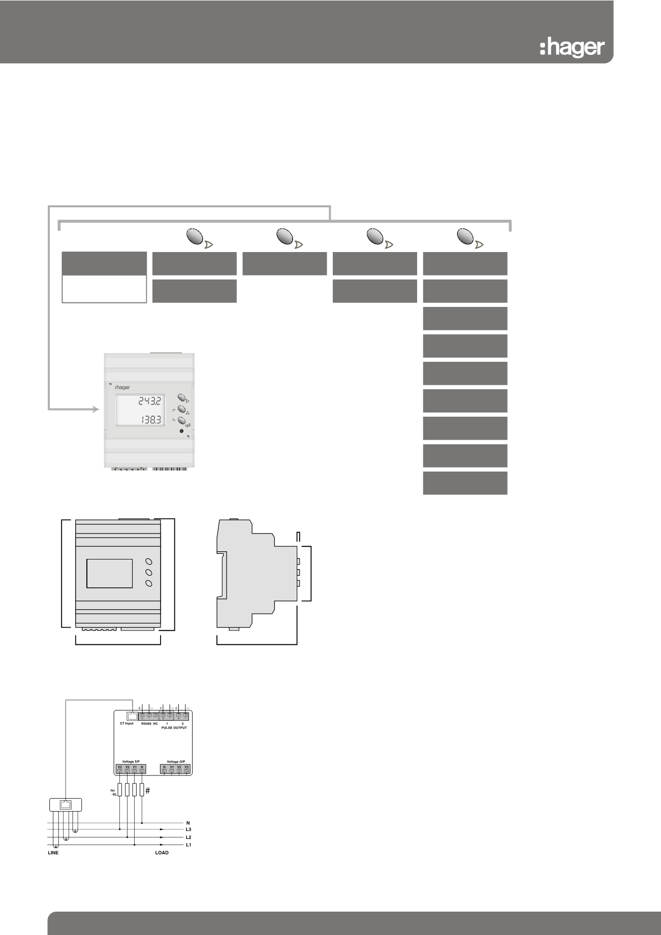
Multifunction Power Meter - Single CT Connection
DIN Rail Mounting - LCD Display - JKM01
Function Diagram
Dimension Diagrams (mm)
Please allow space above and below the meter for cable connections.
67
70
90
95
45
2
Home Page
(Unit will default to this
page after 60 seconds)
Power Factor 3 Phase Average
Frequency Average
L - N Voltage and Current
x 4
x 3
Voltage
Line to Line Per Phase
Power Factor 3 Phase Average
Frequency Average
L - L Voltage and Current
Power Factor Three Phases
Frequency
Voltage
Line to Neutral Per Phase
x 1
3 Phase Average
Line to Neutral Voltage
3 Phase Active Energy - kWh
Active Power
Three Phases
Reactive Power
Three Phases
Apparent Power
Three Phases
Active Power
Total
Reactive Power
Total
Apparent Power
Total
Active Power
Max. Demand
Current
Per Phase
x 2
Apparent Power
Max. Demand
Button Selection
100%
JKM01
PAGE
1 2 3 4 5 6 7
Current
Input
1
PRG
INT
8 9 10 11 12 13 14 15 16 17 18 19
L-N
kW h
Avg
V
• 4 Module DIN rail mounting
• Single phase or 3 phase (4 wire)
network balanced or unbalanced load
• Built-in energy pulse output and
RS485 MODBUS communication
• Wide range of measured parameters
(see table below)
• High quality backlit LCD display
• 330mV current transformer input
• Active energy class 1 (EN62053-21)
• Reactive energy class 2 (EN62053-23)
• THD up to 31st harmonic for voltage
and current
• 3-phase: 140…460Vac measured
voltage
• Single phase: 80…265Vac measured
voltage
• Self supplied auxiliary
• Programmable CT ratio 5…10,000A
• Programmable VT ratio
• Frequency 45/65Hz
• Selectable CT phase correction allows
reversal of L1 and L3
• Weight 190g
1
1