
1.93
Data is subject to errors and technical modifications.
Earth Fault Relays
Technical Data
Commercial
Distribution
Non-Adjustable
Adjustable
HR500
HR502 HR510 HR520 HR522
HR523
HR525/HR534
HR440
HR441
Supply Voltage ~50/60Hz
220-240V
Residual Voltage ~50/60Hz
500V Maximum
Power Absorbed
3VA
5VA
Output
Volt Free Contacts
Contact Rating
6A / 250V AC-1
Sensitivity I∆n
30mA
300mA 30mA / 100mA / 300mA / 500mA /
1A / 3A / 10A
500mA /
1A / 3A /
5A / 10A /
20A / 30A
30mA / 100mA /
300mA / 500mA /
1A / 3A / 5A / 10A
/ 30A
30mA / 100mA / 300mA
/ 500mA / 1A / 3A
Instantaneous / Time Delay
Instantaneous
Instantaneous or
Time Delay 0.1 -
0.3 - 0.4 - 0.5 - 1
- 3 seconds
Instantaneous or Time
Delay 0.1 - 0.2 - 0.25 - 0.3 -
0.4 - 0.5 seconds
Instantaneous or
Time Delay 0.02
- 0.1 - 0.3 - 0.4 -
0.5 - 1 - 3 - 5 - 10
seconds
Instantaneous or Time
Delay 0.1 - 0.3s - 0.5s -
0.75s - 1s
Torroid Withstand Capacity
50kA / 0.2s
Distance between Torroid and
Relay
50 Meter Maximum
Relay Cable Connection
• Rigid
• Flexible
1.5mm
2
to 10mm
2
1mm
2
to 6mm
2
Torroid Cable Conection
• Rigid
• Flexible
1.5mm
2
to 4mm
2
1mm
2
to 2.5mm
2
Relay
• Working Temperature
• Storage Temperature
-10ºC to +55ºC
-25ºC to +40ºC
-5ºC to +55ºC
-25ºC to +40ºC
Torroid
• Working Temperature
• Storage Temperature
-10ºC to +70ºC
-40ºC to +70ºC
-10ºC to +70ºC
-40ºC to +70ºC
Main Characteristics
“Reset” Button
When pressed, the output remains switched and return to normal is obtained
by either: by pressing the “reset” clear pushbutton or cutting off the power
supply. If the “reset” button is not pressed the device remains in the fault
position.
Test Button
Pressing the test button allows a fault simulation which operates the relay and
the output contacts.The fault level display is shown by an LED on the front of
the product.
l∆n Selector
Sensitivity setting: 0.03A instantaneous
0.1A/0.3A/1A and 3A time delay
Time Delay Selector
Adjustable time setting - instantaneous / 0.13s / 0.3s / 1s and 3s
Sealable Settings
A sealable cover prevents interference once the settings have been made.
Standard Output (1 C/O contact)
Switching to state 1 on:
• Failure of the core/relay connection
• Fault current in the monitored installation
Positive Safety Outlet (1 C/O contact)
Switching to state 1: Switching on the power
Switching to state 0: Failure of the core/relay connection
fault current in the monitored installation
failure of relay supply
internal failure of relay
Optical scale display by 5 LEDs of the fault in % of I ∆n
Optical scale display by (5 LEDs) of the fault in % of I ∆n
Common pin 6:
State 1 : output terminal 8
State 0 : output terminal 4
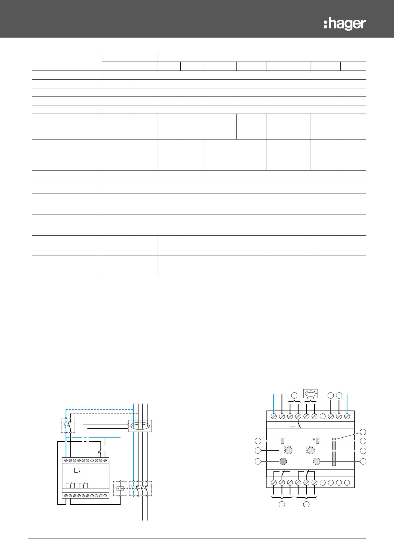
1. Reset push button
2. Test push button
3. Fault signal LED
4. Device on indicator
5. Sensitivity setting
6. Time delay setting
7. Standard output
8. Safety output
9. Prealarm output
10. Remore reset
11. Optical scale
N L1 L2 L3
11 12 13 14
1 2 3 4
15 16 18 19 20
5 6
HR 425
11 12 13 14
1 2 3 4
15 16
18 19 20
5 6
On
5
15
30
45
60
75
Test
Reset
Dt(s)
0
0,1
0,3
0,4 0,51 3
IDn(A)
0,03
0,1
0,3
0,5 1 3 10
4
7
5
3
6
1
2
8
9
10
11
10
reset
test
N L1 L2 L3
11 12 13 14
1 2 3 4
15 16 18 19 20
5 6
HR 425
11 12 13 14
1 2 3 4
15 16
18 19 20
5 6
On
5
15
30
45
60
75
Test
Reset
Dt(s)
0
0,1
0,3
0,4 0,51 3
IDn(A)
0,03
0,1
0,3
0,5 1 3 10
4
7
5
3
6
1
2
8
9
10
11
10
reset
test


