


 535 / 759

Technical Hotline
+44 (0)1268 563720
LIGHTING CONTROLS
535
For a full range of corresponding products,
see pages 208-210 in the product selector.
K1400M
INSTALLATION:
The dimmer module is designed for mounting into distribution and
consumer units containing 35 mm DIN rail according to EN50022.
Please observe the following points during installation:
● All master and slave dimmers must be connected to the same supply
phase.
● The mains supply to the dimmer(s) must be protected by a suitable fuse
or MCB rated no greater than 16A
● Do not exceed maximum control line length of 100m and do not run
slave control lines parallel to mains and network cables.
● Always observe the transformers recommended loading guidelines.
● Load transformers at or close to their full rated capacity. Do not connect
a small load to a larger transformers, (e.g. a 35W lamp on a 600VA
transformer)
● Ensure that slaves are wired to the correct control terminals and that
the polarity is observed
rhöhte
Vorsicht! Kontamination
Vorsicht! Kontamination
Vorsicht, Gefahr durch
Abqu tschen
Vorsicht, Gefahr durch
Abschneiden
Vorsicht, Gefahr durch
Abstürzen
efahr durch
offe
Vorsicht, Gefahr durch
elektrischen Strom
Vorsicht, Gefahr durch
elektrischen Strom
Vorsicht, Gefahr durch
elektromagnetische
Strahlung
Vorsicht, Gefahr durch
explosionsgefährliche
Stoffe
Vorsicht, Gefahr durch
feuergefährliche Stoffe
efahr durch
fe
Vorsicht, G fahr durch
heiße Oberfläche
Vorsicht, Gefahr durch
Laserstrahlung
Vorsicht, Gefahr durch
Radioaktivität
Vorsicht, Gefahr durch
Rutschen
Vorsicht, Gefahr durch
Stolpern
efahr durch
Vorsicht, Warnung vor
Vorsichtig verschieben!
Während der
Wandbrände nicht von
Wandbrände von unten
Important:
Always use the same type of load on each dimmer
module. Do not combine different load types to the same dimmer
Control Wiring for operating Modes 1-6:
Control switches T1-3 for operating modes 1-6 should be push-to-make
momentary contact switches.
Up to 10 operating switches may be wired in parallel with Neon indicators
being allowed on control line T1 only
Example1:
Multiple control buttons:
L
T
T1
T
T2
T
T
T
T3
T
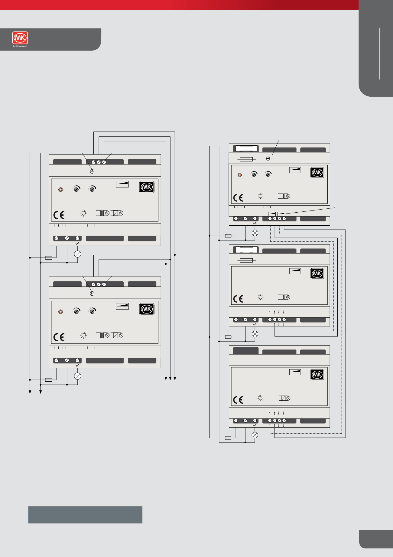
Example 2
: Wiring for Multiple Master Dimmers with common Central-ON
and Central-OFF
L
N
T T
T
T
T1 T2 T3
L N
T1 T2 T3
L N
MASTER DIMMER 1
MASTER DIMMER 2
Load
Load
T1 = Separate Dimming control for each master
T2 = Central-ON for both master dimmers
T3 = Central-OFF for both master dimmers
Control Wiring for operating Mode 7:
Control switch T1 for operating mode 7 should be a standard single pole
light switch with dimming via the rotary 0/1-10V potentiometer connected
between 0-10V and Gnd on the Master dimmer
L
N
T1 T2 T3
0-10V
Gnd
L N
Gnd
0-10V
Control input
0...10V
Button input
T1 - T3
Mains connection
220-240V~ / 50Hz
220V~ / 60Hz
Load
Switch
MASTER DIMMER
L N
F
K1401M
1kW Leading Edge Dimmer - Master
For use with K1401S and K1402S slave modules
®
R, L
ε
220/240V~
50/60Hz
IEC60669-2-1
50061977-001
60-1000VA
50-900VA
S1 S2 S3
L N
0-10V
0-10V
Gnd
Gnd
T1
T2
T3
Mode
1
5
3 7
8 2
6 4
0
Universal Dimmer - Master/Slave
0 units configured s slaves
R, L, C
ε
220-240V~ / 50Hz
220V~ / 60 Hz
EN 60669-2-1
50061976-001
60-1000VA
50-900VA
P1
P2
®
®
F
F
K1401M
1kW Leading Edge Dimmer - Master
For use with K1401S and K1402S slave modules
®
R, L
ε
220/240V~
50/60Hz
IEC60669-2-1
50061977-001
60-1000VA
50-900VA
S1 S2 S3
L N
0-10V
0-10V
Gnd
Gnd
T1
T2
T3
Mode
1
5
3 7
8 2
6 4
0
Universal Dimmer - Master/Slave
0 units configured s slaves
R, L, C
ε
220-240V~ / 50Hz
220V~ / 60 Hz
EN 60669-2-1
50061976-001
60-1000VA
50-900VA
P1
P2
®
®
F
220-240V~ / 50Hz
220V~ / 60Hz
To additional Slave
Dimmer Modules
Control connection (S1-S3)
slave dimmer
Master-dimmer
operating mode 1-7
To additional Slave
Dimmer Modules
Control connection (S1-S3)
slave dimmer
Operating mode 8
INSTALLATION:
The dimmer module is designed for mounting into distribution and
consumer units containing 35 mm DIN rail according to EN50022.
Please observe the following points during installation:
● All master and slave dimmers must be connected to the same supply
phase.
● The mains supply to the dimmer(s) must be protected by a suitable fuse
or MCB rated no greater than 16A
● Do not exceed maximum control line length of 100m and do not run
slave control lines parallel to mains and network cables.
● Always observe the transformers recommended loading guidelines.
● Load transformers at or close to their full rated capacity. Do not connect
a small load to a larger transformers, (e.g. a 35W lamp on a 600VA
transformer)
Vorsicht! Erhöhte
Strahlung
V rsicht! Kontamination
Vorsicht! Kontamination
Vorsicht, Gefahr durch
Abqu tschen
Vorsicht, Gefahr durch
Abschneiden
Vorsicht, Gefahr durch
Abstürzen
Vorsicht, Gefahr durch
ätzende Stoffe
Vorsicht, Gefahr durch
elektrischen Strom
Vorsicht, Gefahr durch
elektrischen Strom
Vorsicht, Gefahr durch
elektromagnetische
Strahlung
Vorsicht, Gefahr durch
explosionsgefährliche
Stoffe
Vorsicht, Gefahr durch
feuergefährliche Stoffe
Co
Co
mo
Up
bei
Ex
L
Ex
and
L
N
Co
Co
ligh
bet
L
N
+12V
L N
+12V
0-10V
Gnd
SE
T1
T2
T3
Mode
1
5
3 7
8 2
6 4
T5A H250V~
A1 B1 A2 B2 Slave-Out
R,L
R,C
K1401M
1kW Leading Edge Dimmer - Master
For usewithK1401S andK1402S slavesmodules
R,L
60-1000VA
50-900VA
P1
P2
®
®
EN 60669-2-1
50061977-001
ε
220-240V~ / 50Hz
220V~ / 60 Hz
F
L N
T5A H250V~
IN Out
IN Out
Slave
A AB B
K1401S
1kW Leading Edge Dimmer - Slave
For usewithK1401MandK1402Mmastermodules
R,L
60-1000VA
50-900VA
®
®
EN 60669-2-1
50061978-001
ε
220-240V~ / 50Hz
2 0V~ / 60 Hz
F
L N
IN Out
IN Out
Slave
A AB B
K1402S
1kW Trailing Edge Dimmer - Slave
For usewithK1401M andK1402Mmastermodules
R,C
®
®
60-1000VA
50-900VA
EN 60669-2-1
50061980-001
ε
220-240V~ / 50Hz
220V~ / 60 Hz
F
L N
F
F
F
220-240V~ / 50Hz
220V~ / 60Hz
Control connection (A,B)
slave dimmer
Master-dimmer operating Mode 1 – 8
K1401M
High Power Dimmer
Technical
WIRING DEVICES