


 534 / 759

 mkelectric.co.uk
LIGHTING CONTROLS
534
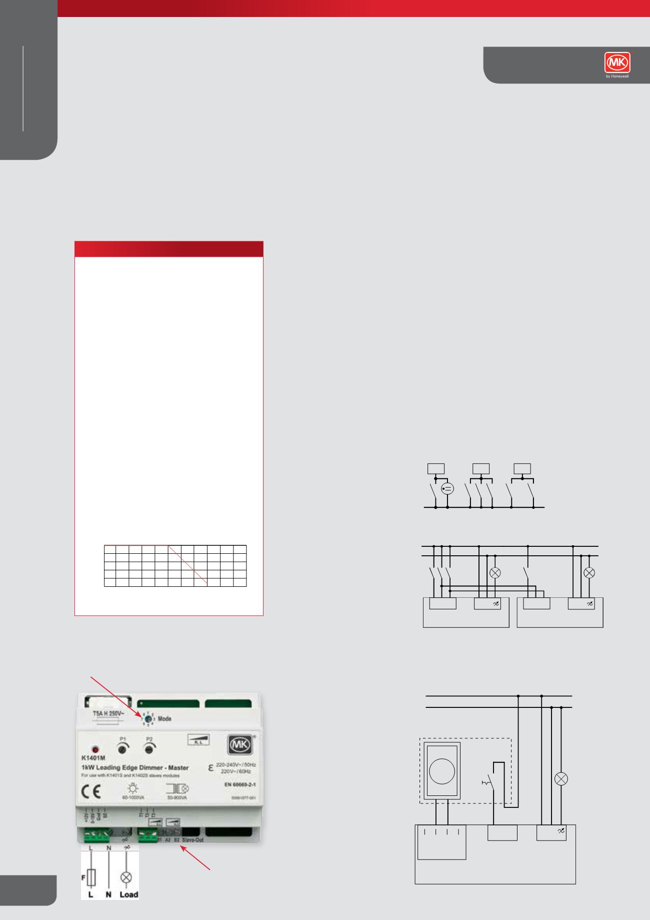
Connection Diagram
Operating Mode
Selector Switch
Slave
Connection
Terminals
INSTALLATION:
The dimmer module is designed for mounting into distribution and
consumer units containing 35 mm DIN rail according to EN50022.
Please observe the following points during installation:
● All master and slave dimmers must be connected to the same supply
phase.
● The mains supply to the dimmer(s) must be protected by a suitable fuse
or MCB rated no greater than 16A
● Do not exceed maximum control line length of 100m and do not run
slave control lines parallel to mains and network cables.
● Always observe the transformers recommended loading guidelines.
● Load transformers at or close to their full rated capacity. Do not connect
a small load to a larger transformers, (e.g. a 35W lamp on a 600VA
transformer)
● Ensure that slaves are wired to the correct control terminals and that
the polarity is observed
Important:
Always use the same type of load on each dimmer
Control Wiring for operating Modes 1-6:
Control switches T1-3 for operating modes 1-6 should be push-to-make
momentary contact switches.
Up to 10 operating switches may be wired in parallel with Neon indicators
being allowed on control line T1 only
Example1:
Multiple control buttons:
L
T
T1
T
T2
T
T
T
T3
T
Example 2
: Wiring for Multiple Master Dimmers with common Central-ON
and Central-OFF
L
N
T T
T
T
T1 T2 T3
L N
T1 T2 T3
L N
MASTER DIMMER 1
MASTER DIMMER 2
Load
Load
T1 = Separate Dimming control for each master
T2 = Central-ON for both master dimmers
T3 = Central-OFF for both master dimmers
Control Wiring for operating Mode 7:
Control switch T1 for operating mode 7 should be a standard single pole
light switch with dimming via the rotary 0/1-10V potentiometer connected
between 0-10V and Gnd on the Master dimmer
L
N
T1 T2 T3
0-10V
Gnd
L N
Gnd
0-10V
Control input
0...10V
Button input
T1 - T3
Mains connection
220-240V~ / 50Hz
220V~ / 60Hz
Load
Switch
MASTER DIMMER
L N
F
K1401M
1kW Leading Edge Dimmer - Master
For usewithK1401S andK1402S slavemodules
®
R,L
ε
220/240V~
50/60Hz
IEC60669-2-1
Made inGermany
50061977-001
60-1000VA
50-900VA
S1 S2 S3
L N
0-10V
0-10V
Gnd
Gnd
T1
T2
T3
Mode
1
5
3 7
8 2
6 4
0
Universal Dimmer - Master/Slave
0 units configured s slaves
R,L,C
ε
220-240V~ /50Hz
220V~ / 60Hz
EN60669-2-1
Made inGermany
50061976-001
60-1000VA
50-900VA
P1
P2
®
F
K1401M
1kW Leading Edge Dimmer - Master
For usewithK1401S andK1402S slavemodules
®
R,L
ε
220/240V~
50/60Hz
IEC60669-2-1
Made inGermany
50061977-001
60-1000VA
50-900VA
S1 S2 S3
L N
0-10V
0-10V
Gnd
Gnd
T1
T2
T3
Mode
1
5
3 7
8 2
6 4
0
Universal Dimmer - Master/Slave
00 units configured s slaves
R,L,C
ε
220-240V~ /50Hz
220V~ / 60Hz
EN60669-2-1
Made inGermany
50061976-001
60-1000VA
50-900VA
P1
P2
®
220-240V~ / 50Hz
220V~ / 60Hz
To additional Slave
Dimmer Modules
Control connection (S1-S3)
slave dimmer
Master-dimmer
operating mode 1-7
To additional Slave
Dimmer Modules
Control connection (S1-S3)
slave dimmer
Operating mode 8
Standards and approvals
All High Power Dimmer modules comply with
EN 60669-2-1
TECHNICAL SPECIFICATION
ELECTRICAL
MAINS SUPPLY
220-240V / 50Hz
220V / 60 Hz
TYPE OF LOADS
Fused GLS Tungsten filament lamps. Dimmable
wirewound or electronic low voltage transformers of
good quality. Inductive loads (i.e. conventional
wire-wound transformers, etc.) must not be
connected to the trailing edge dimmers.
Warning: These dimmer modules are not suitable
for use with fluorescent lamps or energy saving
lamps.
PHYSICAL
AMBIENT OPERATING TEMPERATURE
-5°C to +40°C
REDUCTION OF THE DIMMER POWER
If this product is used in an ambient temperature
exceeding 40ºC, the maximum allowable load will
need to be reduced according to the table below.
This will prevent the internal thermal protection in the
product from activating and switching the load off.
-10 0 10 20 30 40 50 60 70 80 90 100
0
200
400
600
800
1000
Ambient temperature in °C
Maximum Rated Load (W)
Description
These dimmer modules are designed for mounting into distribution and consumer
units containing 35mm Din rail according to EN50022. All master and slave
dimmers must be connected to the same supply phase. Key points to observe
during installation:
l
The mains supply to the dimmer(s) must be protected by a suitable fuse or MCB rated no
greater than 16A
l
Do not exceed maximum control line length of 100m and do not run slave control lines
parallel to mains and network cables
l
Always observe the transformers recommended loading guidelines
l
Load transformers at or close to their full rated capacity. Do not connect a small load to a
larger transformers, (e.g. a 35W lamp on a 600VA transformer)
l
Ensure that slaves are wired to the correct control terminals and that the polarity is observed
Note: The outputs of the K1402M and K1402S trailing edge dimmers may be connected in
parallel to drive a single load greater than 1kW/900VA.
INSTALLATION:
The dimmer module is designed for mounting into distribution and
consumer units containing 35 mm DIN rail according to EN50022.
Please observe the following points during installation:
● All master and slave dimmers must be connected to the same supply
phase.
● The mains supply to the dimmer(s) must be protected by a suitable fuse
or MCB rated no greater than 16A
● Do not exceed maximum control line length of 100m and do not run
slave control lines parallel to mains and network cables.
● Always obse ve th tr nsformers recommended loading guidelines.
● Load tr nsformers at or clo e to their full rat d capacity. Do not connect
a small lo d to a larger transformers, (e.g. 35W lamp on a 600VA
transformer)
● Ensure that slaves are wired to the correct control terminals and that
the pola ity is observed
Important:
Always use the same type of load on each dimmer
module. Do not combine diff rent load types to the same dim r
Control Wiring for operating Modes 1-6:
Control switches T1-3 for operating odes 1-6 should be push-to-make
momentary contact switches.
Up to 10 operating switches may be wired in parallel with Neon indicators
bei g allo ed on contr l line T1 only
Example1:
Multiple control buttons:
L
T
T1
T
T2
T
T
T
T3
T
Example 2
: Wiring for Multiple Master Dimmers with common Central-ON
and Central-OFF
L
N
T T
T
T
T1 T2 T3
L N
T1 T2 T3
L N
MASTER DIMMER 1
MASTER DIMMER 2
Load
Load
T1 = Separate imming control for each master
T2 = Central-ON for both master dimmers
T3 = Central-OFF for both master dimmers
Control Wiring for operating Mode 7:
Control switch T1 for operating mode 7 should be a standard single pole
light switch with dimming vi the rotary 0/1-10V potentiometer connected
between 0-10V and Gnd on the Master dimmer
L
N
T1 T2 T3
0-10V
Gnd
L N
Gnd
0-10V
Control input
0...10V
Button input
T1 - T3
Mains connection
220-240V~ / 50Hz
220V~ / 60Hz
Load
Switch
MASTER DIMMER
L N
F
K1401M
1kW Leading Edge Dimmer - Master
ForusewithK1401S andK1402S slavemodules
®
R,L
ε
220/240V~
50/60Hz
IEC60669-2-1
Made inGermany
50061977-001
60-1000VA
50-900VA
S1 S2 S3
L N
0-10V
0-10V
Gnd
Gnd
T1
T2
T3
Mode
1
5
3 7
8 2
6 4
0
1kW Universal Dimmer - Master/Slave
0 units configured s slaves
R,L,C
ε
220-240V~ / 50Hz
220V~ / 60Hz
EN 60669-2-1
Made inGermany
50061976-001
60-1000VA
50-900VA
P1
P2
®
F
K1401M
1kW Leading Edge Dimmer - Master
ForusewithK1401S andK1402S slavemodules
®
R,L
ε
220/240V~
50/60Hz
IEC60669-2-1
Made inGermany
50061977-001
60-1000VA
50-900VA
S1 S2 S3
L N
0-10V
0-10V
Gnd
Gnd
T1
T2
T3
Mode
1
5
3 7
8 2
6 4
0
Universal Dimmer - Master/Slave
0 units configured s slaves
R,L,C
ε
220-240V~ / 50Hz
220V~ / 60Hz
EN 60669-2-1
Made inGermany
50061976-001
60-1000VA
50-900VA
P1
P2
®
220-240V~ / 50Hz
220V~ / 60Hz
To additional Slave
Dimmer Modules
Control connection (S1-S3)
slave dimmer
Master-dimmer
operating mode 1-7
To additional Slave
Dimmer Modules
Control connection (S1-S3)
slave dimmer
Operating mode 8
Control Wiring for operating
Modes 1-6 (K1400) and
Modes 1-7 (K1401/K1402)
Control switches T1-3 should
be push-to-make momentary
contact switches.
Up to 10 operating switches
may be wired in parallel with
Neon indicators being allowed
on control line T1 only.
Control Wiring for operating
Mode 7 (K1400) and Mode 8
(K1401/K1402)
Control switches T1 should
be a standard single pole light
switch with dimming via the
rotary 0/1-10V potentiometer
connected between 0-10V and
Gnd on the Master dimmer.
High Power Dimmer
Technical
WIRING DEVICES