


 528 / 759

 mkelectric.co.uk
528
PHYSICAL (ALL PRODUCTS)
AMBIENT OPERATING TEMPERATURE
–5°C to +40°C
IP RATING
IP4X
MAX. INSTALLATION ALTITUDE
2000 metres
TECHNICAL SPECIFICATION
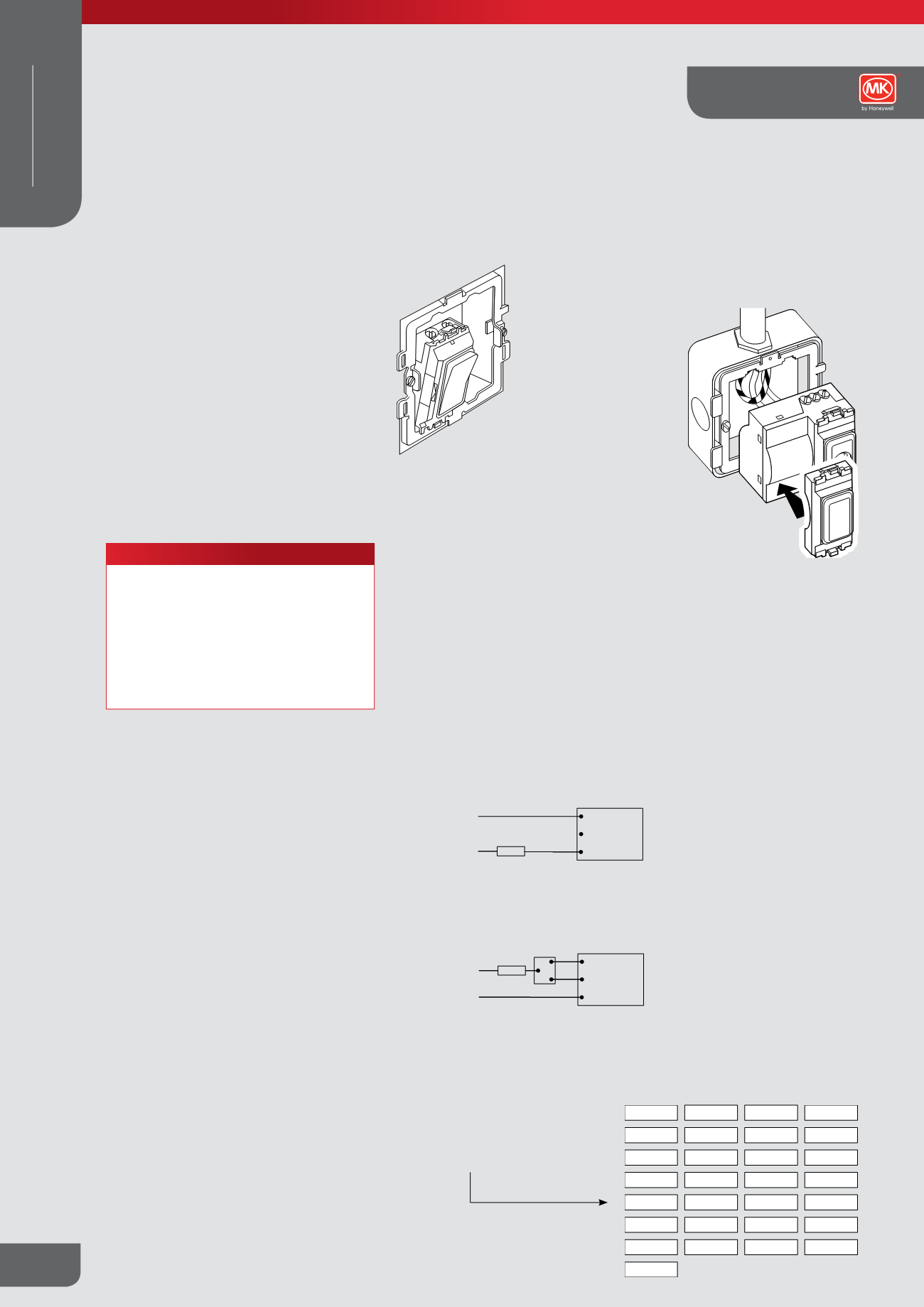
Modular Switching System
1
Locate bottom tab of
module in base
of grid.
2
Module pushes into
place at top with
a ‘click.
3
To remove module,
press tab at top and
lever forward.
Typical mounting
arrangement
N
L
L
1
L
2
C
Two-way switching
(only one dimmer can be used)
L
1
L
2
C
Load
DIMMER
Supply 230V a.c. - 50Hz
2wayswitch
L
N
One-way switching
L
1
L
2
C
Load
DIMMER
Supply 230V a.c. - 50Hz
Wires must be connected to the correct Dimmer terminals.
Supply Earth must only be connected to the installation metalwork
and not to any of the terminals on the dimmer module.
pool
lights
bar
conferenceroom
office
reception
bell
push
bedroom dining area
kitchen
lounge
air conditioner
water heater
dish washer
store
front
middle
bottom
rear
back
top
landing
hall
porch
toilets
ladies
gents
exterior
Standards and approvals
Switch modules
BS EN 60669-1:1999
Indicator units
BS 5733:2010
Dimmer switches
Dimmers comply with BS EN 60669-2-1
Accessory modules
Single non-isolated, TV/FM socket outlet,
BS 3041 Part 2: 1977
Installation
General
Cut cables to length and make earth
connections to grid. Earth: bond grid frame to
metal mounting box. Grid frames are screwed
to back box, modules wired as appropriate and
simply clipped into grid frame by hand. No tools
are necessary. The front plate is screw fixed to
the grid frame to finish the assembly.
To remove or change modules, simply remove
front plate. Individual modules fit perfectly into
the frontplate in flush fitting installations.
Grid mounting
An integral design feature automatically ensures
that the modules fit perfectly into the frontplate in
flush fitting installations.
Some manual adjustment may be required for
surface mounted applications or low profile
ranges (Edge
TM
).
Rocker window labels
The following labels are available for
insertion into window rockers.
Dimmers
The two module size dimmer can be fitted to any
grid mounting frame over 1 gang. The supplied
blank module can be placed at the required pitch
to fill in the second position on the grid.
To avoid overheating when using more than
one dimmer in the same Grid Plus enclosure
it is recommended that the dimmers are
preferentially mounted on the bottom row on
6, 8, 9, 12, 18 and 24 gang enclosures, before
mounting on any other rows and its load
adjusted in accordance with the information
provided in the Load Adjustment Table 1 at the
bottom of the next page.
Dimmer wiring diagram
Grid Plus Technical
WIRING DEVICES
MODULAR