


 439 / 759

Technical Hotline
+44 (0)1268 563720
439
Echo™ is a registered trademark of Novar ED&S Limited
Transmitters, Receivers and Accessories
Echo
™
Installer Guide
1. INTRODUCTION
The MK Echo
™
range of products are different from all other
products in MK’s Wiring Devices portfolio in so far as the “switches”
are RF transmitters which communicate with Switch Receivers. It is
the Switch Receivers that actually switch the mains power.
Echo
™
Transmitters send an RF signal at 868.3 MHz. The unique
feature of these products is that the signal transmission is made
without the need for mains power, or batteries.
Compared to installing hard-wired systems, wireless systems are
much simpler and provide the flexibility to relocate or add to a system.
A symbol is visible on all Switch Receivers to indicate the position
of the antenna. Although not always possible, the best reception
will always be achieved if the front face of the Transmitter is
directly facing the surface of the Switch Receiver on which the
antenna symbol is shown.
2. PRINCIPLES OF RADIO SIGNALS IN BUILDINGS
Echo
™
Transmitters send wireless transmissions to the Echo
™
Switch Receivers. The receiver checks the incoming signal for
accuracy and uses the data to control outputs. Radio signals are
electromagnetic waves; hence the signal becomes weaker the
further it travels.
Please note that RF signals also decrease in strength when they
pass through certain materials between the transmitted signal and
the receiver.
While radio waves can penetrate a wall, they are dampened more
than on a direct line-of-sight path. A few examples of different
types of wall and the realistic typical reduction in signal strength
that can be seen are:
MATERIAL
ATTENUATION
Wood, plaster, uncoated glass,
with no metal content
0 – 10%
Brick, pressed board
5 – 35%
Ferro-concrete
10 – 90%
Metal, aluminium lining
90 – 100%
In practice, this means that the material used in a building must be
taken into consideration during any assessment for radio coverage.
Here are some typical guideline figures when using Logic Plus
style Transmitters with plastic frontplates:
Line-of-sight connections:
typically 30m range in corridors,
or up to 100m in halls
Plasterboard walls / dry wood:
typically 30m range, through 5 walls
Brick walls / aerated concrete:
typically 20m range, through 3 walls
Ferro-concrete walls / ceilings:
typically 10m range, through 1 ceiling
All other Transmitters in the range that have metal frontplates, do
of course cause a reduction in the signal strength and therefore the
transmission distance. Generally, the line of site distance in a hall is
reduced from 100m described above for Logic Plus
™
, down to 30m.
3. SCREENING
Objects made of metal, such as wall reinforcements, the metal
foil often used in certain forms of insulation, or metallised heat
protected glass, reflect electromagnetic waves and thus create
what is known as a radio shadow and thereby a reduction in
transmission distance.
The main factors decreasing coverage include:
l
A Transmitter mounted on metal surfaces
(typically 30% loss of range).
l
Transmitters
with metal frontplates (typically 60% loss of range).
l
Hollow lightweight walls filled with insulating wool on metal foil.
l
Inserted ceilings with panels made of metal or carbon fibre.
l
Lead glass or glass with metallised coating, steel furniture.
Please note: Fire-safety walls, elevator shafts, staircases and
supply areas should be considered as screening.
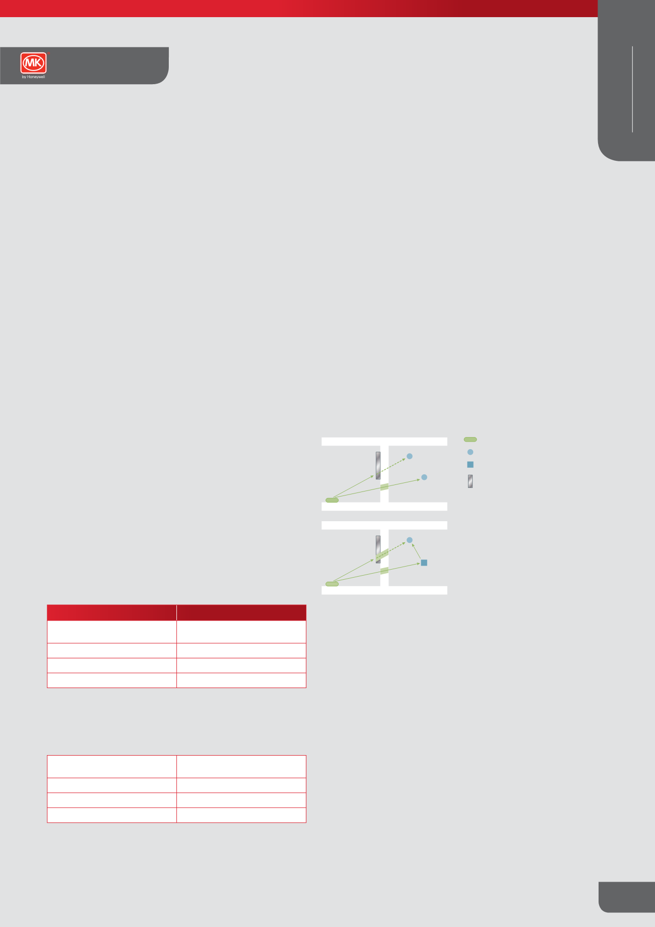
WALLS
WALLS
Transmitter
Receiver
Repeater
Metal
sheet
✓
✗
✓
✗
Simple example of a possible screening problem.
Depending on the material used to build the walls and assuming
the distance between the transmitters and receivers are within
specification, the illustrations above show a typical screening problem.
For the best range performance a minimum distance of 10mm to
20mm should be allowed from the whole length of the antenna
to any conductive objects, which effectively means the area
surrounding the Switch Receiver module.
Avoid screening by repositioning the Transmitter and / or Switch
Receiver away from the screening objects (radio shadow), or if
this is not possible, by using a Repeater.
MK Echo™ Technical
WIRING DEVICES
WIRELESS