


 474 / 582

BETA Monitoring
Monitoring of Electrical Values
5
TT3 fuse monitors
13/18
Siemens ET B1 · 10/2008
*
You can order this quantity or a multiple thereof.
13
■
Overview
Fuse monitors serve to monitor all types and versions of melting
fuses that cannot be equipped with a fault signal contact. This
enables integration in fault signaling circuits or a central alarm in
order to improve plant availability.
■
Benefits
•
Increase in plant availability because fuse failures – which
could cause considerable damage to the plant – are detected
in plenty of time.
•
A fuse failure is detected even if the load is switched off.
This ensures the highest level of plant availability.
■
Technical specifications
■
Selection and ordering data
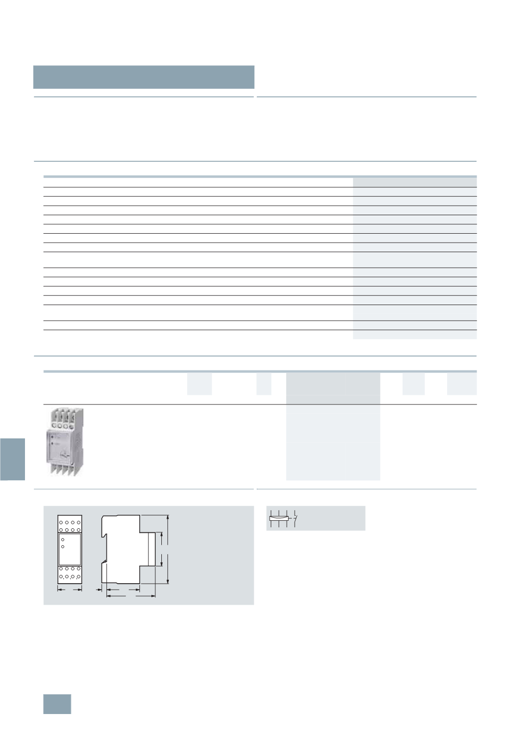
■
Dimensional drawings
■
Schematics
5
TT3 170
Standards
IEC 60255; DIN VDE 0435-110
Rated control voltage U
c
V
3
x 380 ... 415 AC
Operating range
× U
c
0.8 ... 1.1
Rated frequency
Hz
50 ... 400
Internal resistance
of measuring paths
/
V
> 1000
Max. permissible rear feed
%
90
Response/release time
ms
< 50
Rated impulse withstand voltage U
imp
Input/output
kV
> 4
Rated operational voltage U
e
V AC
250
Rated operational current
I
e
AC-1
A
4
Electrical service life
AC-11
In switching cycles at 1 A 1.5 × 10
5
Terminals
±
screw (Pozidriv)
1
Conductor cross-sections
Rigid, max.
mm
2
2
× 2.5
Flexible, with end sleeve, min.
mm
2
1
× 0.5
Permissible ambient temperature
°C
-20 ...
+45
Resistance to climate
Acc. to EN 60068-1
20/45/4
U
e
I
e
U
c
MW DT Order No.
Price
per PU
PG PU PS*/
P. unit
Weight
per PU
approx.
V AC A
3
V AC
Unit(s) Unit(s) kg
Fuse monitors
For all low-voltage fuse systems. Can be used in
asymmetric systems afflicted with harmonics and
regenerative feedback motors. Signal also for
disconnected loads.
230 4
380 ... 415 2
}
5
TT3 170
027 1
1
0.150
36
L1L2 L3
14
L1 L2 L3
15
5 43
64
45
90
I2_11512
L3 L2 14
L1
13
L3'
L2'
L1'
© Siemens AG 2008