


 470 / 582

BETA Monitoring
Monitoring of Electrical Values
5
TT6 current relays
13/14
Siemens ET B1 · 10/2008
13
■
More information
Direct measurement,
transformer measurement
All current relays can be connected with direct measurement or
through transformers.
N potential
Versions 5TT6 113 to 5TT6 120 can be connected with a
separate N potential.
Response time
Current relays are not circuit-protection devices for lines. They
switch with a delay in the ms range.
Overload capability
Independent of the set measuring range and set measured value,
current relays can be permanently overloaded up to 15 A or
20
A for 3 s, even up to 20 A or 30 A
.
Buildings/object-safe guiding lights
In the approach corridors of planes, high buildings must be
fitted with position lighting. The same planning instructions apply
to the monitoring of this type of lighting and runway lighting as
the monitoring of emergency lighting.
Monitoring of emergency lighting with incandescent lamps
The function of emergency lighting according to DIN VDE 0108
must be checked at regular intervals. The operational current is
continuously monitored using current relays. The lighting can
either be integrated in the general lighting system or just supplied
on demand with emergency current.
The current relay is set so that it switches on at the max. lamp
current. If an incandescent lamp fails, a fault is signaled.
Monitoring of motors
If the warning is sent early enough, the fault can be eliminated
before the motor starts to overheat and the circuit breaker
switches the motor off.
Current relays reliably safeguard the monitoring of fault-free
running motors and, in some cases are more suitable than a
voltage relay, which is geared more towards motor protection.
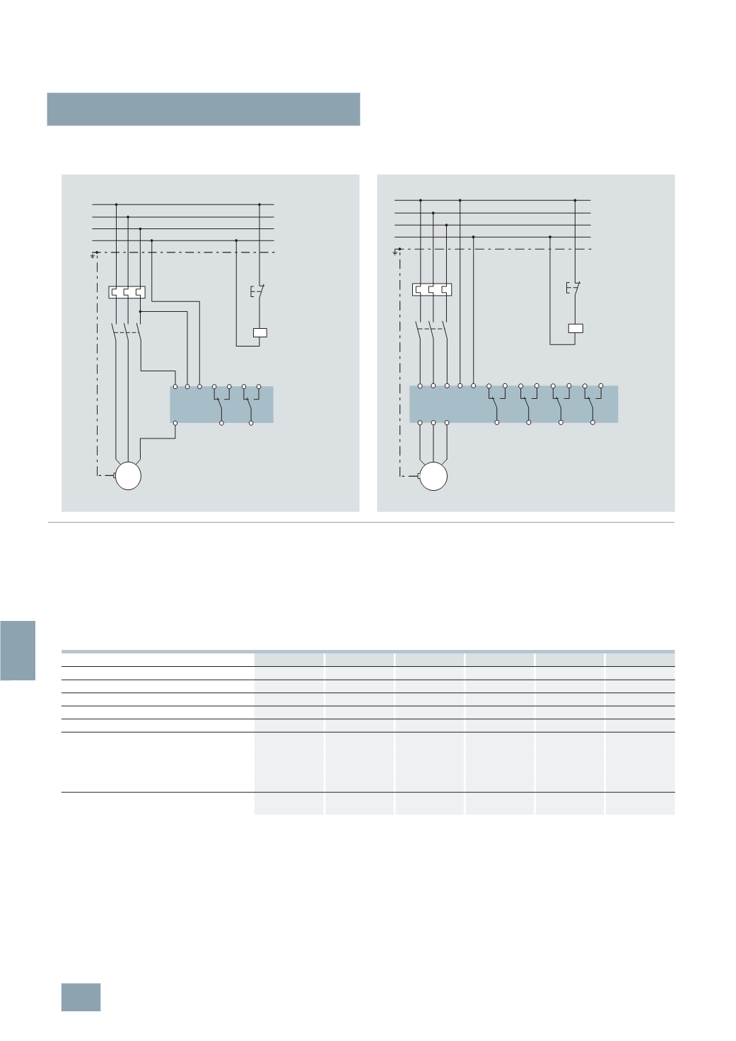
Switching example:
5
TT6 114 with direct measurement up to 15 A
for overcurrent measurement
Switching example:
5
TT6 120 with direct measurement up to 5 A
for undercurrent/overcurrent measurement
i
5
TT6 114
A1 A2
k
K1
PE
M
L1
L2
L3
N
PE
K1
12 14 22 24
11
21
3 230/400
V AC
I2_07559a
5
TT6 120
A1 A2
K1
PE
M
L1
L2
L3
N
PE
K1
12 14 22 24
11
21
i
k
1
i
2
i
3
k
2
k
3
1
32 34 42 44
31
41
I
min
I
max
3 230/400
V AC
I2_07561a
Device overview
5
TT6 111
5
TT6 112
5
TT6 113
5
TT6 114
5
TT6 115
5
TT6 120
Undercurrent
✓
--
✓
--
✓
✓
Overcurrent
--
✓
--
✓
✓
✓
Single-phase
✓
✓
✓
✓
✓
--
Three-phase
--
--
--
--
--
✓
Separate N potential
--
--
✓
✓
✓
✓
Measuring ranges: Jumper:
0.1 ... 1
A
Z1 – Z2
--
--
✓
✓
✓
--
0.5 ... 5
A
Z1 – Z3
--
--
✓
✓
✓
✓
1 ... 10
A
Z1 – Z4
✓
✓
✓
✓
✓
--
1.5 ... 15
A
Z1 – Z3 – Z4
--
--
✓
✓
✓
--
Can be programmed over jumpers
--
--
✓
✓
✓
--
Contacts
1
CO contact
✓
✓
--
--
--
--
2
CO contacts
--
--
✓
✓
✓
✓
© Siemens AG 2008