


 471 / 582

BETA Monitoring
Monitoring of Electrical Values
5
TT6 current relays
13/15
Siemens ET B1 · 10/2008
13
*
You can order this quantity or a multiple thereof.
Example: screw conveyor
Hard objects in screw conveyors, e.g. in sewage treatment
plants, often lead to the conveyor system getting blocked up.
Appropriately set, the current relay signals over its contact(s)
that a hazardous situation has occurred and threatens to block
the motor.
Example: stirrer
As with the conveyor processes, changes to the viscosity can
lead to an overload of the motors.
Example: crane motor control system
The current monitoring of the main motor (hoisting motor) ensures
that the electrical holding brake is not released until the main
motor is in operation and the load is held.
Example: dust extraction
In the interests of work safety and to protect against massive
dust development, it is essential to ensure that the dust extraction
system is working perfectly before a saw or sanding machine is
switched on.
Planning the monitoring of an incandescent lamp
Current relays have a hysteresis of approx. 4 %. The smallest
lamp must not exceed the set measuring range by more than
8 %.
Example: 12 Lamps à 100 W = 1200 W, which corresponds to a
current of approx. 5.2 A. If a lamp fails, the current drops by
0.4
A. This 0.4 A corresponds to 8 % of the set measured value
5.2
A.
Response time
The response time of the fault signal is produced by the "Adjustable
switching delay" (see the technical specifications) and an additional
delay, which is determined from the actual current and the set
value.
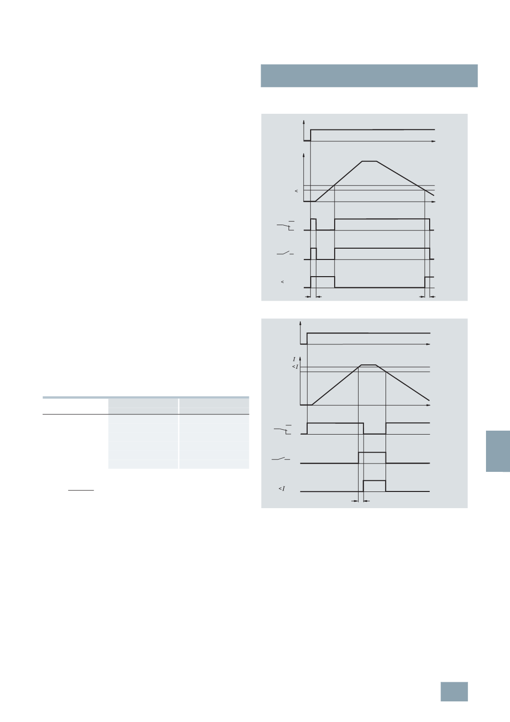
Function chart for
5
TT6 1 undercurrent relay signal
5
TT6 1 overcurrent relay signal
F
Pick-up
Drop-out
ms
ms
1
10
250
2
70
70
5
120
30
10
180
15
20
220
10
30
240
12
F =
I
act
I
meas
I
act
:
Actual current
I
meas
:
Set current threshold value to be measured
Pick-up: With an overcurrent relay, the contact 11 – 14
(21 – 24)
to the fault signal closes when the actual current flowing
is higher than the switching threshold.
The relay picks up.
Drop-
out:
With an undercurrent relay, the contact 11 – 12
(21 – 22)
to the fault signal closes when the actual current flowing
is lower than the switching threshold.
The relay drops out.
0
1
)
)
#
#
)
)
#
#
&
.
&
.
2
2
$
$
3
*
/
4
5
6
)
)
#
#
)
)
#
#
&
.
&
.
2
2
$
$
3
*
/
4
© Siemens AG 2008