


 480 / 582

BETA Monitoring
Monitoring of Electrical Values
5
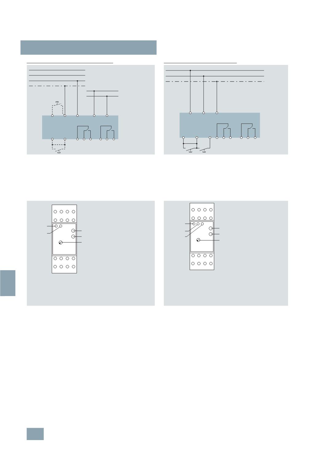
TT3 insulation monitors
for industrial applications
13/24
Siemens ET B1 · 10/2008
13
5
TT3 470 for AC and three-phase systems
5
TT3 471 for direct voltage systems
Front views
Direct interference voltage
While direct interference voltages do not damage the devices
they often interfere with conditions in the measuring circuit. In a
system being monitored, only one insulation monitor should be
connected. This must be taken into account if gateways are
used.
System capacitances against the protective ground do not corrupt
the insulation measurement as these are implemented with direct
current. However, it may extend the response time in the event
of an insulation fault, primarily in the case of the time constant RE
times CE. The auxiliary voltage of the insulation monitor can be
taken from a separate system or from the one being monitored.
In this case the voltage range of the auxiliary power input must
be taken into account.
LEDs:
•
Green LED lights up if actuating voltage U
c
is applied
•
Red LED lights up in the event of an insulation fault.
Leakage capacitance
The insulation monitor can be installed in systems with higher
leakage capacitance against PE. In the case of high-resistance
alarm values, a transient alarm signal may occur when switching
on the monitored system due to an existing ground leakage ca-
pacitance.
For the following set values for R, these values for the
CE capacitance are approx.:
•
R = 200 k : CE > 0.8 F
•
R = 50 k : CE > 2.0 F
•
R = 20 k : CE > 4.5 F
In these applications, you should work without an alarm storage.
Due to the measuring function with bridge circuit, the insulation
monitor does not respond in the event of a simultaneous, exactly
symmetric ground fault of L+ and L-. However, exactly symmetric
ground faults are highly unlikely in practice.
LEDs:
•
Green LED lights up if actuating voltage U
c
is applied
•
Red LED 1 lights up for insulation fault L+ against PE
•
Red LED 2 lights up for insulation fault L- against PE.
The actuating voltage of terminals A1 – A2 can be taken from the system
being monitored. However, in this case it is important to ensure compliance
of the voltage range with the technical specifications.
With a jumper LT1 – LT2: a fault signal is not stored; the device is automatically
released again if the insulation resistance improves.
Without a jumper LT1 – LT2: the error message is stored; pressing the
pushbutton terminals LT1 – LT2 clears the fault signal.
Pressing the pushbutton terminals PT – PE simulates a fault.
The actuating voltage for the terminals L+ and L- is also the measurement
voltage.
With a jumper LT – X1: a fault signal is not stored; the device is automatically
released again if the insulation resistance improves. Without a jumper
LT – X1: the error message is stored; pressing the pushbutton terminals
LT – X1 clears the fault signal.
Pressing the pushbutton terminals PT – X1 simulates a fault.
5
TT3 470
5
TT3 471
L1
L2
L3
PT PE L
PE
A1
A2
LT1 LT2 11 12 14 21 22 24
L
N
I2_11520b
L+
L-
PT
L-
PE
PE
LT X1
11 12 14 21 22 24
L+
I2_11521a
I2_11971
PE PT LT1 LT2
L
A1 A2
T1
T2
12
22
14 11 24 21
E1
LED green:
LED red:
E1:
T1:
T2:
status display (ON)
insulation fault (AL)
alarm value adjuster (RAL)
Test
Reset
LED red
LED green
I2_11972
PE PX X1 LT
L+
T1
T2
12
22
14 11 24 21
L–
E1
LED 1 red
LED green
LED 2 red
LED green:
LED 1 red:
LED 2 red:
E1:
T1:
T2:
status display (ON)
insulation fault L– (RE–)
insulation fault L+ (RE+)
alarm value adjuster (RAL)
Test
Reset
© Siemens AG 2008