


 267 / 582

BETA Protecting
SR60 Busbar Systems
Distribution board components
5/3
Siemens ET B1 · 10/2008
5
■
Overview
The use of busbar systems with their versatile rail-adaptable
connection, switching and installation devices is an ideal and
cost-effective electrotechnical enhancement of modern distribution
boards due to their small footprint, compact design and quick
assembly contacts. Mounting is implemented on longitudinal
stays. The busbar spacing is 60 mm.
■
Benefits
•
Only a few distribution board components are required to
ensure the integration of busbars in the distribution board.
This saves time and space
•
The touch protection cover is sealable as standard and is
quick and easy to attach to the supports thanks to the use of
quick-release locking technology.
■
Technical specifications
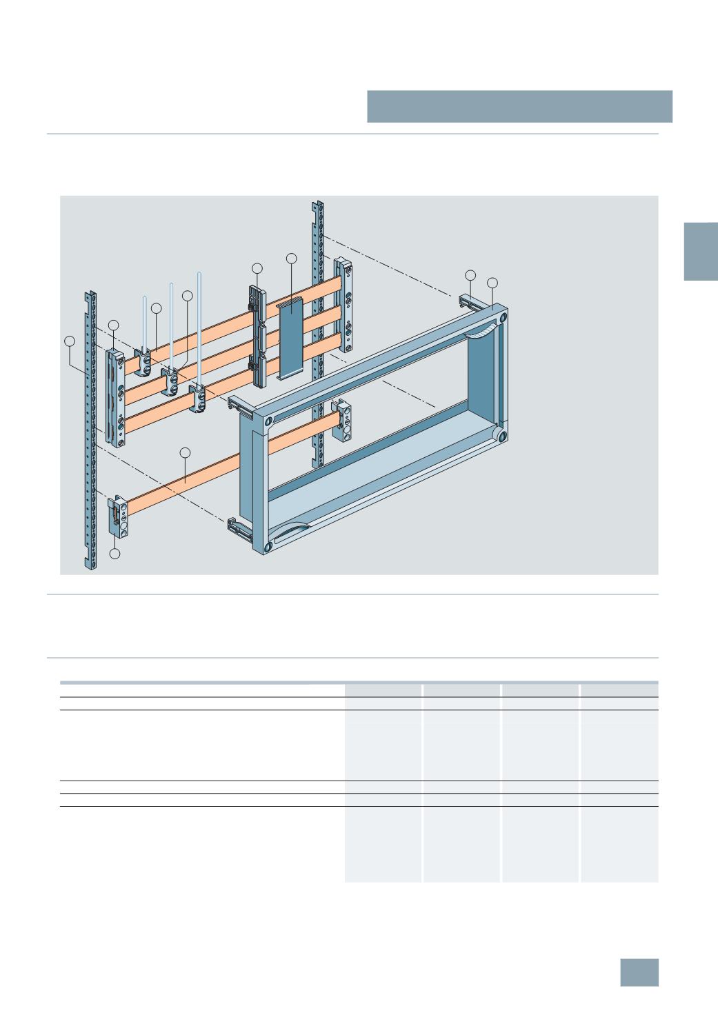
I201_13633
8
7
9
5
6
3
3
4
2
1
Infeed, connection modules, three-phase
5
SH3 538
5
SH3 535
8
US19 21-1BA00 8US19 21-1AA00
Busbar center-to-center clearance
mm 60
60
60
60
Current carrying capacity of the terminal points
A
80
560
300
440
The specified current carrying capacities reflect the thermal load
capability of the terminal points under favorable conditions (with
the largest conductors it is possible to connect). This does not
invalidate the assignment of conductor cross-sections and current
carrying capacities as defined in national and international
specifications.
Tightening torques
Nm --
30
8 ... 10
12 ... 15
Clamping space W × H
mm --
--
10
× 15
15
× 15
Conductors that can be used
mm
2
1.5 ... 16
Cu, re, rm, f, f+AE
(
reduction of the
max. conductor
cross-sections may
be required)
150 ... 300
Cu, Al (connections
with aluminum
conductors are not
maintenance free),
rm, sm, f
6 ... 50 (70)
Cu, rm, f, f+AE
(
reduction of the
max. conductor
cross-sections may
be required), la.
Cu 6 × 9 × 0.8
35 ... 120
Cu, rm, f, f+AE
(
reduction of the
max. conductor
cross-sections may
be required), la.
Cu 6/10 × 15.5 ×
0.8
$
Longitudinal stays
%
Busbar supports, three-phase
&
Cu busbars
(
Terminals
)
Support for blanking covers
*
Blanking cover
+
Supports
,
Touch protection cover
-
Busbar supports, single-phase
© Siemens AG 2008