


 272 / 582

BETA Protecting
SR60 Busbar Systems
Distribution board components
5/8
Siemens ET B1 · 10/2008
5
Dynamic rated short-circuit strength
The electrodynamic load of the busbars depends on the level of
short-circuit current, the length of the busbar section through
which the current flows, the support spacing of the busbar
supports and, of course, on the distance between the busbars
themselves. This is because, for example, if an LV HRC fuse is
connected upstream to the busbars in the protective device, the
let-through current i
D
is the maximum current to flow through this
protective device. The value i
D
depends on the maximum system
short-circuit current and the current-limiting action of the protective
device used. The permissible let-through values of the protec-
tive equipment are specified by the manufacturers in the form
of a current limitation diagram as a function of the so-called
prospective short-circuit current (r.m.s. value of the possible
rated short-circuit current for the system).
You will find the current-limiting characteristics for the fuse links
in the Catalog Add-On ET B1 AO · 2008 BETA Low-Voltage Circuit
Protection, Characteristic Curves for Catalog ET B1
.
For busbar supports with busbars of 12 × 5 mm to 20 × 5 mm,
the distance between the holders of the support spacing should
be adapted to suit the bars in the distribution board and should
not exceed 250 mm if possible. When using busbars of
25
× 5 mm, 30 × 5 mm, 12 × 10 mm to 30 × 10 mm, the dis-
tance can also be up to 500 mm. In the case of larger distances,
subcarriers must be fitted as increased support spacing reduces
the dynamic stability.
It is essential to ensure that the permissible current carrying
capacity of the individual busbars is not exceeded. A center
infeed is required in the limit range. However, the infeed can also
be carried out at both ends of the busbar.
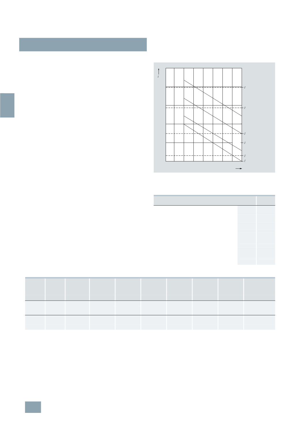
Diagram of the dynamic short-circuit strength of the busbars
i
D
:
Let-through values (kA) of the LV HRC fuse links, operational class
gL/gG with rated current 200 A to 630 A for a prospective short-circuit
current
I
p
= 120 kA.
Planning dimensions
Number of built-in components that can be mounted
Width
mm MW
NEOZED bus-mounting bases D02
Covers
27
1.5
Covers, extra wide
36
2.0
Covers, double width
54
3.0
DIAZED bus-mounting bases DII
Covers
42
2.3
Covers, double width
84
4.7
DIAZED bus-mounting bases DIII
Covers
57
3.2
Covers, double width
114
6.3
NEOZED bus-mounting switch disconnectors
27
1.5
LV HRC fuse switch disconnectors size 00
108
6
30
40
50
60
70
80
150 200 250 300 350 400 450 500 550
D
[
kA]
n
200
A
n
250
A
n
315
A
n
400
A
n
500
A
n
630
A
20
x5
12
x5
20
x10
12
x10
30
x5
30
x10
Distance between busbar support in mm
Busbar dimension
mm
Let-through current
of the fuse links
Operating class
gL/gG
I2_07483a
Height
Width
Cutout width D02/63 A
5
SH5 241
D02/63 A
5
SH5 242
D02/63 A
5
SH5 243
DII/25 A
5
SH2 042
DIII/63 A
5
SH2 242
LV HRC00
(3
NP40 76)
5
SG7 230 bus-
mounting switch
disconnectors
D02
mm mm mm
(27
mm wide) (36 mm wide) (54 mm wide) (42 mm wide) (57 mm wide) (108 mm wide) (26.8 mm wide)
300
250
216
8
6
4
5
3
1
8
500
466
17
12
8
11
8
4
17
750
716
26
19
13
17
12
6
26
450
250
216
8
6
4
5
3
1
8
500
466
17
12
8
11
8
4
17
750
715
26
19
13
17
12
6
26
© Siemens AG 2008