




 235 / 543

Circuit-breakers, switch-disconnectors
Diagnostics, communication
2010 CA08103002Z-EN
www.eaton.com17/139
Diagnostics,communication
Diagnostics,communication
Description
Part no.
Article no.
Price
See price
list
Std. pack
Notes
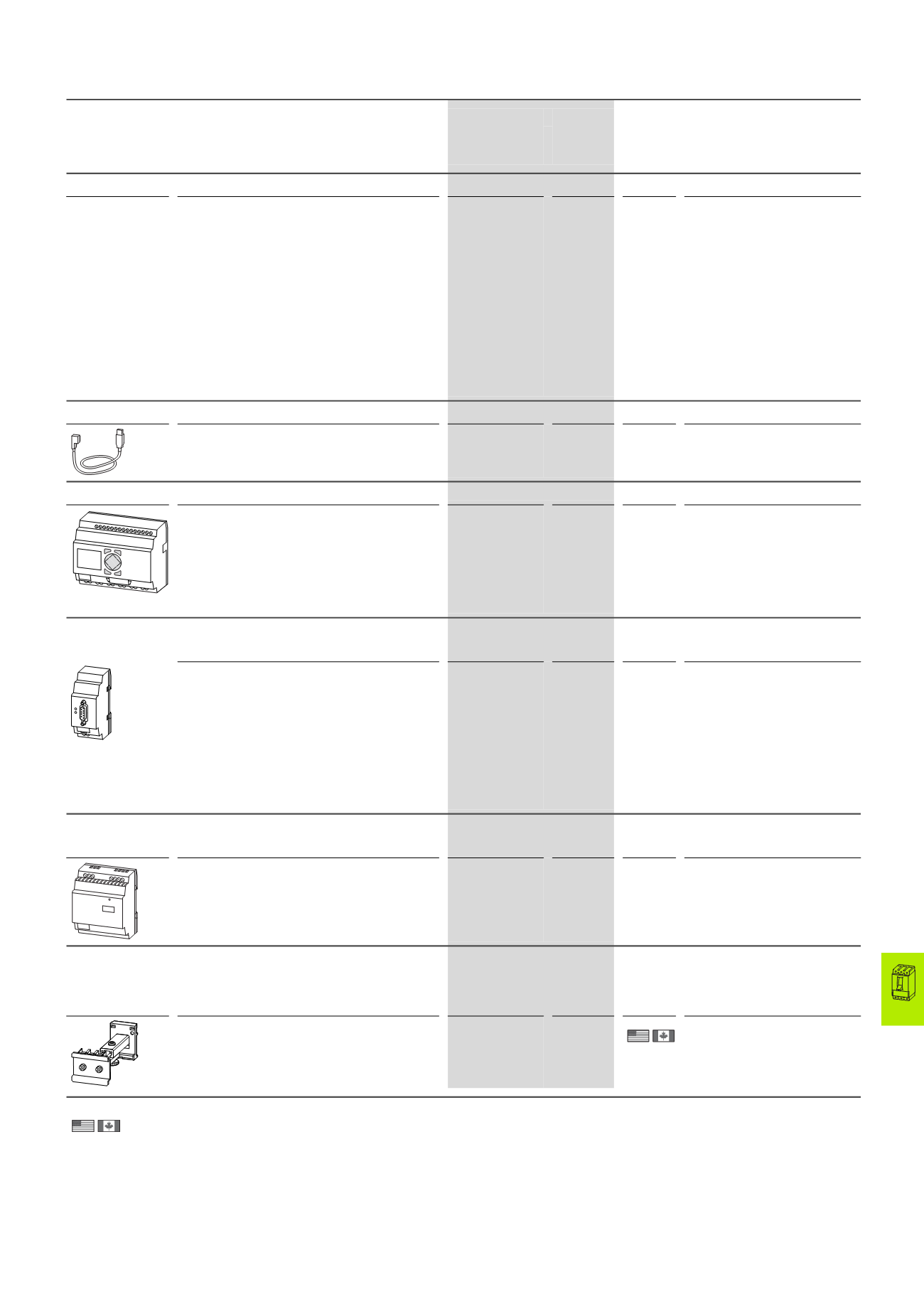
Diagnostics and configuration software for NZM and DMI (local)
PC software for direct connection to all new NZM circuit-
breakers with electronic releases (IEC and UL/CSA
devices) or for direct connection to the DMI module,
including the required connection cable to NZM.
• Protection parameter: online display and curve
display, export option to curve characteristics
program “Moeller CurveSelect”.
• Warning and release messages: reading of
diagnostic memory also in voltage-free state.
• Load currents: display and trend indication.
• Recording and export options to Excel for load
currents and diagnostic messages.
• Configuration of the DMI: motor starter, remote
operator, assignment of the DMI inputs and outputs
and displays.
NZM-XPC-KIT
265631
1 off
Only for use in combination with
circuit-breakers with
electronic
releases.
Download the manual
AWB1230-1459 and demo-software at
www.moeller.net.Order connecting cable to DMI
separately: EASY-USB-CAB.
Connecting cable PC (USB) to DMI
• For transmission of DMI configuration between PC
with XPC-Soft and DMI
• For upgrading DMI firmware
EASY-USB-CAB
107926
1 off
Can also be used for programming
easy small controllers.
Data management interface (DMI module)
• Access to diagnostics and operational data.
• Recording current values, motor starter function, and
setting parameters.
• Control of the circuit-breakers with electronic trip
block.
• Comprehensive remote diagnostic options and
remote operation via fieldbus in combination with a
field Bus connection.
NZM-XDMI612
260217
1 off
Includes connection cable NZM-
XDMI-CAB between NZM and DMI
(length: 2 m).
Only for use in combination with
circuit-breakers with
electronic
releases.
Fieldbus interface for DMI
Connection to the DMI module
• Transfer of phase currents, parameter data, status
data and diagnostics data.
• Transfer of circuit-breaker position (wiring of
auxiliary contacts to DMI inputs).
• Actuation of the DMI motor starter functions and the
NZM remote operator.
• Detection of digital inputs and actuation via field Bus.
• PROFIBUS-DPV1-Slave fieldbus interface. Can be
operated with class 1 and class 2 masters. Addresses
available: 1 to 126.
NZM-XDMI-DPV1
270333
1 off
Connected to the DMI module
and has the same contour
appearance.
Switched-mode power supply unit
For DMI module
• Rated input voltage:
50/60 HZ: 115/230 V AC
• Rated output voltage (residual ripple):
24 V DC (± 3 %)
• Rated output current: 1.25 A
EASY400-POW
212319
1 off
–
Telescopic adapter
For DMI module
For equalization of the mounting depth when rear mounted in CI-K... enclosures
and cabinets.
With 35 mm top-hat rail IEC/EN 60715, adjustable from
75 – 115 mm. Screw and snap fitting.
M22-TA
226161
1 off
–
Information relevant for export to North America
Product Standards IEC/EN 60947-5; UL 508; CSA-C22.2 No. 14-05; CSA-C22.2
No. 94-91; CE marking
UL File No.
E29184
UL CCN
NKCR
CSA File No.
012528
CSA Class No.
3211-03
NA Certification
UL Listed, CSA certified
ESC
OK
DEL
ALT
Power
NZM2, NZM3, NZM4
HPL17139EN