


 268 / 439

7/76
Motor-protective circuit-breakers PKZ2
Motor-protective circuit-breakers
2010
CA08103002Z-EN
www.eaton.comMotor-protectivecircuit-breakers
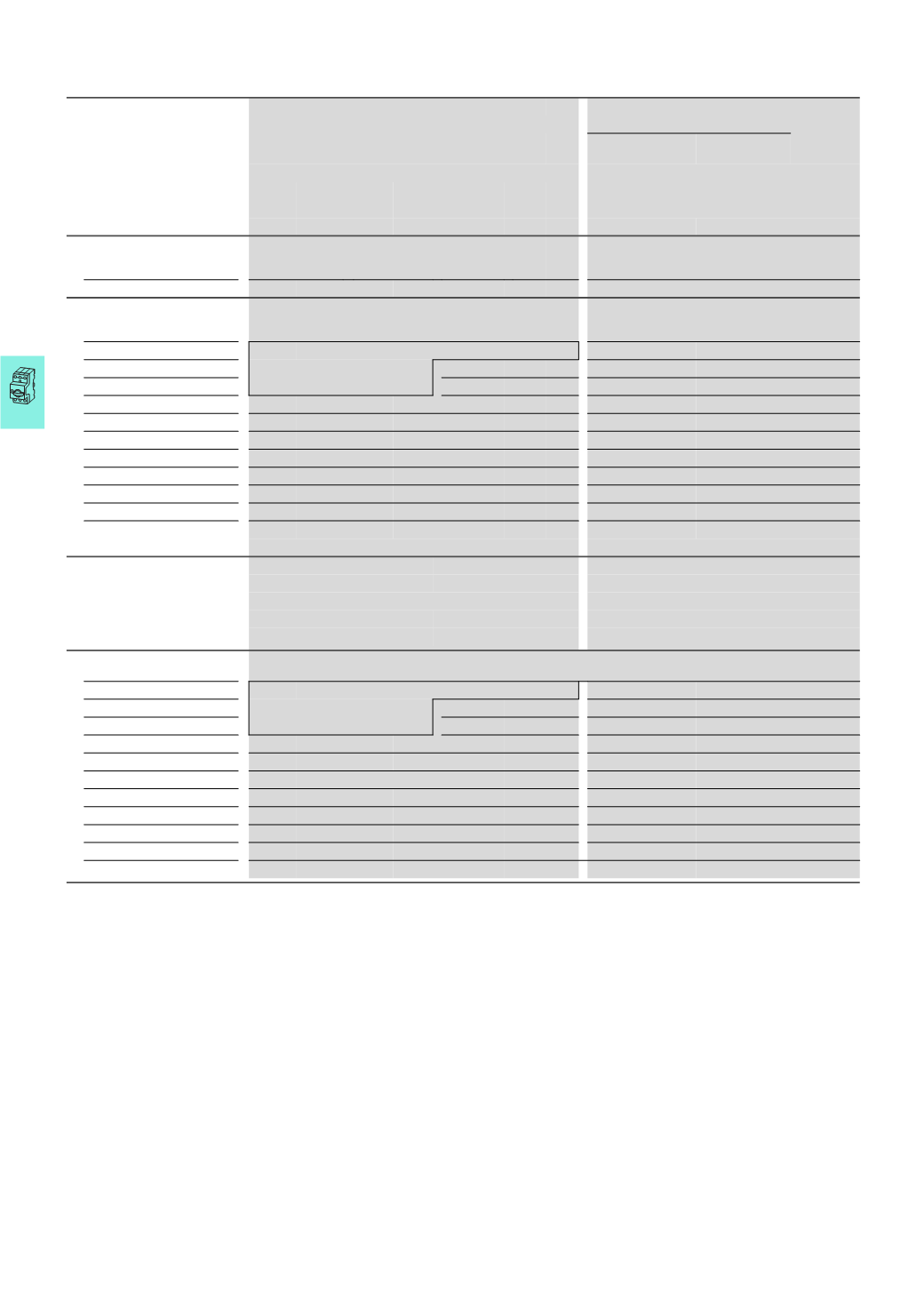
Approved rating data
1)
Maximum motor rating
Setting ranges
UL 508/CSA C 22.2 No. 14
Three-phase current
Overload
releases
Short-circuit-
releases
200
V
230
V
460
V
575
V
208
V
240
V
480
V
600
V
HP
HP
HP
HP
A
A
Basic device
“
Basic device“
In connection with motor protection trip block
ZM-...-PKZ2 ZMR -...-PKZ2
PKZ2
10
15
30
30
Motor protection trip module
with overload relay function
“
Motor Protection Trip Module with overload relay function“
ZMR-0.6-PKZ2
2)
0.4 – 0.6
5 – 8
ZMR-1-PKZ2
½
½
0.6 – 1
8 – 14
ZMR-1.6-PKZ2
¾
1
1 – 1.6
14 – 22
ZMR-2.4-PKZ2
½
½
1
1½
1.6 – 2.4
20 – 35
ZMR-4-PKZ2
1
1
2
3
2.4 – 4
35 – 55
ZMR-6-PKZ2
1½
1½
3
5
4 – 6
50 – 80
ZMR-10-PKZ2
2
3
5
7½
6 – 10
80 – 140
ZMR-16-PKZ2
3
5
10
10
10 – 16
130 – 220
ZMR-25-PKZ2
7½
7½
20
25
16 – 27
200 – 350
ZMR-32-PKZ2
10
10
20
30
24 – 32
275 – 425
ZMR-40-PKZ2
10
15
30
30
32 – 42
350 – 500
Auxiliary contact ZMB
Pilot Duty
D 300, R 300
General Purpose
1.5
A 240 V AC
0.6
A 600 V AC
Terminal capacity
AWG 18 … 14
Torque
1
Nm/9 lb.-in
Motor protection
Trip module
ZM-1.6-PKZ2
2)
0.4 – 0.6
5 – 8
ZM-1-PKZ2
½
½
0.6 – 1
8 – 14
ZM-1.6-PKZ2
¾
1
1 – 1.6
14 – 22
ZM-2.4-PKZ2
½
½
1
1½
1.6 – 2.4
20 – 35
ZM-4-PKZ2
1
1
2
3
2.4 – 4
35 – 55
ZM-6-PKZ2
1½
1
3
5
4 – 6
50 – 80
ZM-10-PKZ2
2
3
5
7½
6 – 10
80 – 140
ZM-16-PKZ2
3
5
10
10
10 – 16
130 – 220
ZM-25-PKZ2
7½
7½
20
25
16 – 27
200 – 350
ZM-32-PKZ2
10
10
20
30
24 – 32
275 – 425
ZM-40-PKZ2
10
15
30
30
32 – 42
350 – 500
Notes
Service factor (SF)
Set value I
r
on the current scale
depending on the load factor
1)
Devices for world markets IEC q UL/CSA.
2)
Calculate motor power in this range according to the
rated operational current.
SF = 1.15 → I
r
= 1 x I
n mot
Stated values to NEC
SF = 1 → I
r
= 0.9 x I
n mot
Table 430 – 150.
Terminal capacity High-capacity compact starters
PKZ2/ZM-.../S,
Motor-protective circuit-breakerPKZ2/ZM-...
Cables
Cu 75 °C, min. AWG 14,
max. AWG 6
Torque
1.8
Nm
PKZ2