


 170 / 439

6/22
Electronic motor protective relay
Selection aid
2010
CA08103002Z-EN
www.eaton.comEngineering
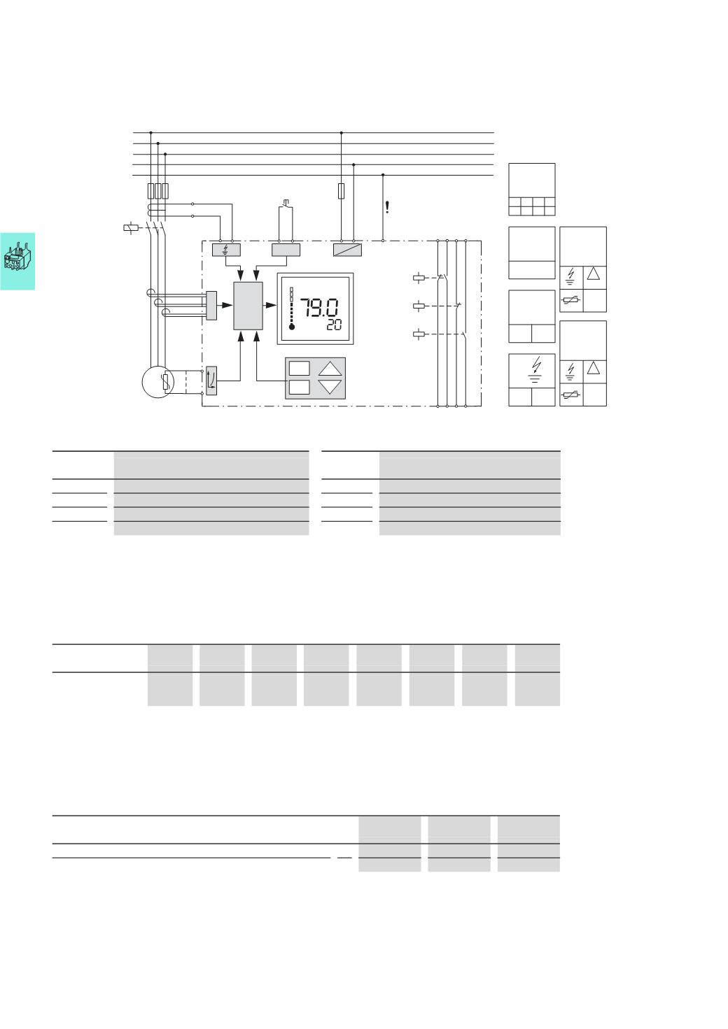
1)
IF: Internal fault
Inputs
Outputs
A 1/A 2
Rated control voltage
95/96
NC overload/thermistor
T 1/T 2
Thermistor sensor
97/98
N/O overload/thermistor
C 1/C 2
SSW core-balance transformer
05/06
NC contact freely assignable
Y 1/Y 2
Remote reset
07/08
N/O contact freely assignable
Switchgear and cable sizing corresponding to the respective starting inertia (CLASS) for ZEV and ZEB
Switchgear is designed according to "CLASS 10" requirements for both normal and overload operation conditions. In order for the
switchgear (circuit-breaker and contactor) and the cables not to be overloaded with long tripping times, they must be overdimensioned
accordingly. The rated operational current, I
e
,
for switchgear and cables can be calculated with the following current factor taking the
tripping class into account:
Trippling class
Class 5
Class 10 Class 15 Class 20 Class 25 Class 30 Class 35 Class 40
Current factor of
rated operational
current I
e
1.00
1.00
1.22
1.41
1.58
1.73
1.89
2.00
Rated motor currents < 1 A
When working with the ZEV-XSW-25 to ZEV-XSW-145 push-through sensors, the motor feeder cables for each phase are pushed
through the corresponding-push-through openings. For motor currents smaller than 1 A, the motor feeder cables are placed in
loops with the ZEV-XSW-25 unit. The specific number of loops depends on the rated motor current.
Number of loops n
4
3
2
Rated motor current I
N
A 0.25…0.32
0.33…0.49
0.5…0.99
Set current on the relay I
E
between the lowest and highest values
A 1.00…1.28
1.00…1.47
1.00…1.98
The device's set current, I
E
,
is calculated as follows: I
E
= n x I
N
5 10 15 20
25 30 35 40
IF
1)
IF
1)
Class
Y1
T1
T2
Y2
C2
C1
A1 A2
95 97 05 07
96 98 06 08
~ =
N
L3
L2
L1
M
3
~
Z2
Z1
l
%
L1 L2 L3
PE
PE
I
e
I
e
> 105%
I
e
> 105%
!
µP
!
1 – 820
A
Mode
Test
Reset
Up
Down
Reset
Menu
ON OFF
Reset
Manual Auto
Class
Fault
Free
parameter 1
Free
parameter 2
Free
parameter
1
Free
parameter
2
ZEV, ZEB