


 174 / 336

Sensors
iProx series
2010 CA08103002Z-EN
www.eaton.comInductive Sensors
3/61
InductiveSensorsiProx series
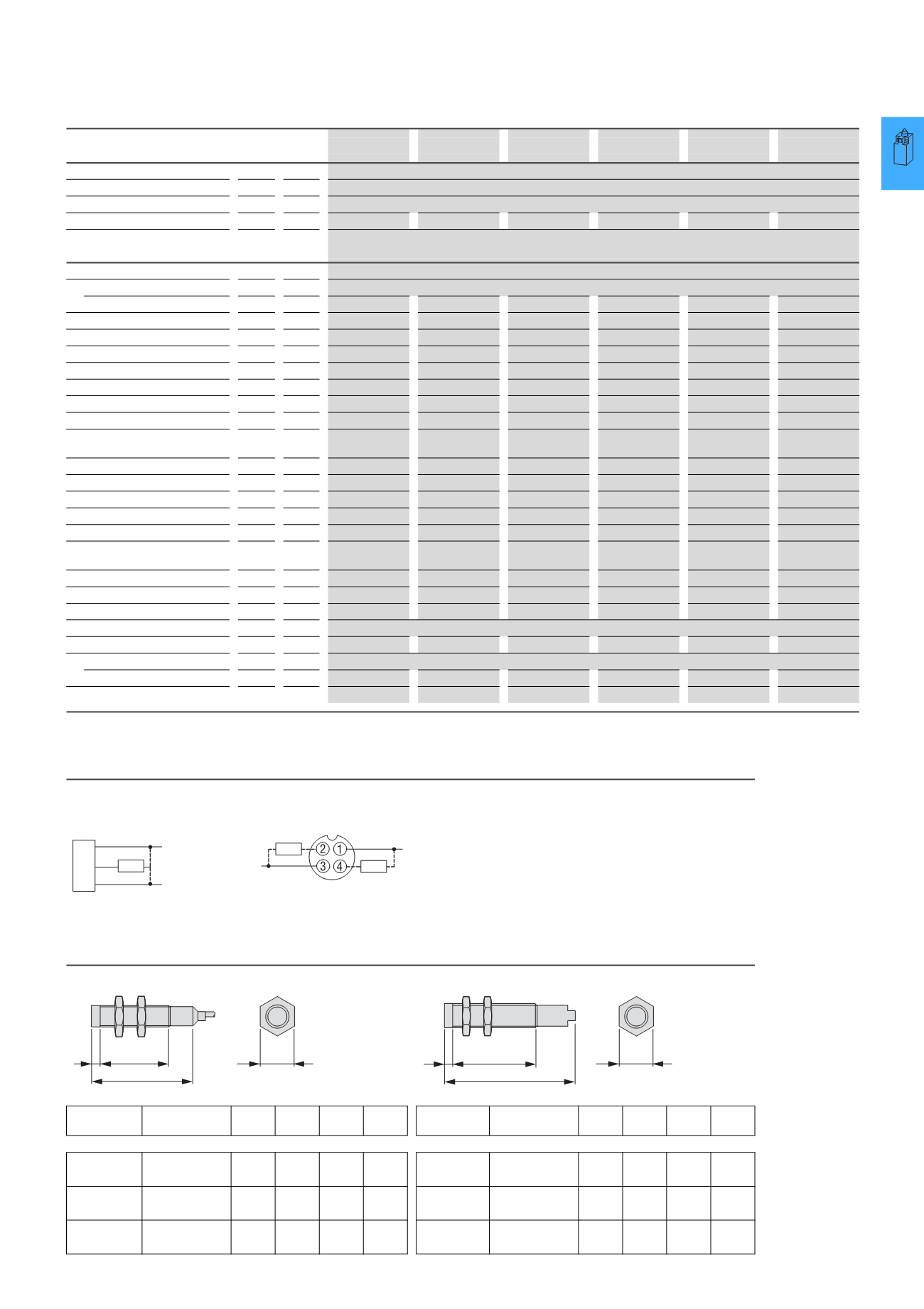
Technical data
Engineering
Dimensions
E59-M12A105
E59-M18A108
E59-M12C110
E59-M30A115
E59-M18C116
E59-M30C129
General
Standards
IEC/EN 60947-5-2
Ambient temperature
°C
-40 - +70
Protection type
IP67
IP69K
IP67
IP69K
IP69K
IP69K
Mechanical shock resistance
30
Shock duration 11 ms
Characteristic values
Rated switching distance
Rated switching distance
S
n
mm 4
8
10
15
18
29
Repetition accuracy of S
n
% 1
1
3
1
3
3
Temperature drift of S
n
% 10
10
10
10
10
10
Switching hysteresis of S
n
% 15
15
15
15
15
15
Sensing range
mm –
–
–
–
–
–
Rated operating voltage
6 - 48 V DC
6 - 48 V DC
6 - 48 V DC
6 - 48 V DC
6 - 48 V DC
6 - 48 V DC
Mains frequency
Residual ripple of U
e
% –
–
–
–
–
–
Operating current in the switched
state at 24 V DC
I
b
mA 15
15
15
15
15
15
Rated operational current
I
e
mA 300
300
300
300
300
300
Voltage drop at I
e
U
d
V
2.5
2.5
2.5
2.5
2.5
2.5
Switching frequency
Hz
580
390
300
240
150
145
Min. load current
I
e
mA 1
1
1
1
1
1
Short-time current (10 ms, 5 Hz)
A
–
–
–
–
–
–
Residual current due to the load in
locked state at 230 V AC or 24 V DC
I
r
mA 0.15
0.15
0.15
0.15
0.15
0.15
Switching state indication
LED Red
Red
Red
Red
Red
Red
Operating voltage display
LED Red
Red
Red
Red
Red
Red
Boundary gain
–
–
–
–
–
–
Protective functions
Short-circuit protection, protection against polarity reversal, wire breakage protection
Function
3-wire
3-wire
3-wire
3-wire
3-wire
3-wire
Construction type
Design (outer dimensions)
M12 x 1
M18 x 1
M12 x 1
M30 x 1.5
M18 x 1
M30 x 1.5
Material
Stainless steel
Stainless steel
Stainless steel
Stainless steel
Stainless steel
Stainless steel
Notes
Further technical data can be found in the Online Catalogue at
www.moeller.netCircuit diagram
59...CO2-D1
E59...CO2-D2
E59...DO1-D1
E59...DO1-D2
Pins 2 and 4 internally interconnected.
2 m connection cable
M12 plug connector
Construction
type
Installation type a
b
c
d
Construction
type
Installation type a
b
c
d
12 mm Flush
62.4 50.3 0.5
17
12 mm Flush
68.7 50.3 0.5
17
Non-flush
62.4 41.6 9
17
Non-flush
68.7 41.6 9
17
18 mm Flush
64.5 50.9 0.5
24
18 mm Flush
69.3 50.9 0.5
24
Non-flush
64.5 37.4 14
24
Non-flush
69.3 37.4 14
24
30 mm Flush
69.6 54.1 0.75 36
30 mm Flush
74.1 54.1 0.75 36
Non-flush
69.6 35.8 19
36
Non-flush
74.1 35.8 19
36
BU
BN
(-)
+V
BK Load
(-)
Load
+V
Load
b
c
d
a
b
c
a
d