


 16 / 20

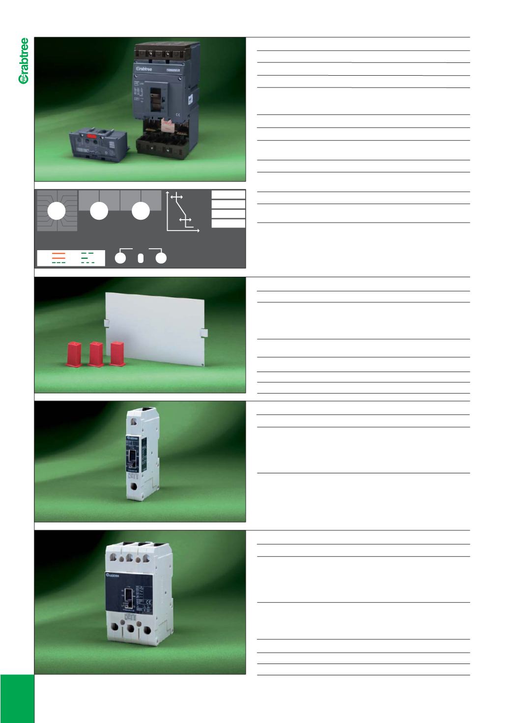
BLANKING PLATES
l
Description LIST No
T2 frame MCCB TP blanking kit
17
T2B
ANCILLIARIES
l
Description
LIST No
3
P Terminal Shields
7
T3A3TS
UVR 230V AC or DC
7
T3AUV/230
4
P Terminal Shields
7
T3A4TS
Padlock kit outgoing
7
T2ALD
Auxilliary
7
T3ACO
Padlock kit incoming
7
T3ALD
UVR 110V AC or DC
7
T3AUV/110
Shunt Trip 24V/48V
Shunt Trip 230V
AC or DC
7
T3AST/48
AC or DC
7
T3AST/230
3
POLE GG FRAME MCCBs
I
Rating (A) LIST No Rating (A) LIST No
15
7
PBGGN315
50
7
PBGGN350
20
7
PBGGN320
60
7
PBGGN360
25
7
PBGGN325
80
7
PBGGN380
30
7
PBGGN330
100
7
PBGGN3100
40
7
PBGGN340
125
7
PBGGN3125
•
Standards: IEC/EN 60947-2
• 25
kA Icu at 415VAC
•
Fixed thermal and magnetic trips
•
Terminal Capacity up to 50mm
2
BLANKING PLATES
I
Description LIST No
GG Frame MCCB SP blanking kit
17
GGB
1
POLE GG FRAME MCCBs
I
Rating (A) LIST No Rating (A) LIST No
15
7
PBGGN115
50
7
PBGGN150
20
7
PBGGN120
60
7
PBGGN160
25
7
PBGGN125
80
7
PBGGN180
30
7
PBGGN130
100
7
PBGGN1100
40
7
PBGGN140
125
7
PBGGN1125
•
Standards: IEC/EN 60947-2
• 25
kA Icu at 240VAC
•
Fixed thermal and magnetic trips
•
Terminal Capacity up to 50mm
2
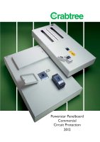
MAIN UNIT MCCBs - 40A TO 250A
I
Description LIST No
250
A 36kA Switching Unit
7
T2S3250
250
A 65kA Switching Unit
7
T2H3250
•
Standards: IEC/EN 60947-2
•
Terminal Capacity 120mm
2
TRIP UNIT OVERLOAD SETTINGS
I
Rated Current
I
n:
100
A
7
T210/OR3
Overload protection
I
r: 40, 43, 46, 48, 50, 55, 58, 61, 63, 69, 72, 76,
80, 87, 91
and 100A
Rated Current
I
n:
160
A
7
T216/OR3
Overload protection
I
r: 63, 69, 72, 80, 87, 91,100, 110, 115, 120, 125,
130, 137, 144, 150
and 160A
Rated Current
I
n:
250
A
7
T225/OR3
Overload protection
I
r: 100, 110, 115, 125, 137, 144,160, 172, 180,
190, 200, 210, 220, 231, 243
and 250A
Restart: T
(0),
T
(
t)
Instantaneous short circuit protection:
I
i = 4 x
I
r,
I
i = 8 x
I
r
The rating of these MCCBs is defined by selection of the appropriate
overcurrent release.
THE SWITCHING UNIT MUST BE FITTED WITH AN OVERCURRENT RELEASE
MODULE.
14
ETU DP
I =250A
CATEGORY A
TRMS
RESTART
n
I (A)
i
I
I (A)
r
TEST
I
r
I
i
172
160
144
137
125
115
110
100
180
190
200
210
220
231
243
250
8
xl
r
4
xl
r
l
r
T
(0)
T
(
t)
l
i
TRIP
>110%
110%
80%
30%
RUN
7
T2S3250 + OR
17
T2B
1
Pole MCCB
3
Pole MCCB
POWERSTAR 250
OUTGO I NG MCCB s