


 76 / 91

TECHNI CAL DATA
L MCCB
76
7T3 FRAME MCCB s TECHNICAL SPECIFICATION
l
7T3 FRAME SPECIFICATION
I
• Specification IEC 60947-2 & IEC 60947-3
• Current Range 100 – 630Amps
• Ue Rated Operation Voltage 690V AC
• Ui Rated Insulation Voltage 690V AC
• Rated Frequency 50/60Hz
• Release Electronic
• Adjustment 0.4 – 1.0 x Trip Unit
Rated Current
• Instantaneous Adjustment Adjustable – see below
• Icu (415V) Short Circuit Breaking Capacity 7T3S 36kA 7T3H 65kA
• Working Environment Both Dry and Tropical
Climates
• Mechanical Endurance 20,000 Cycles
7T3 FRAME FEATURES
I
The 7T3 circuit breaker consists of switching unit and either a range of
different rated electronic trip units, or a disconnector module. The modular
design provides the maximum flexibility as the user can decide not only the
rating but also the function, disconnector or protective device. With a wide
setting bandwidth electronic trip units offer unparalleled functionality.
AVAILABLE OPTIONS
I
• ST UVR
• Aux SW
• Rotary Handle (available on request)
• Padlocking
(See Product Section for selection)
SHORT CIRCUIT BREAKING CAPACITY
I
Ue 7T3S Icu 7T3H Icu
230 V 60 kA 100 kA
415 V 36 kA 65 kA
Ics
= 50% Icu
TRIP UNIT SETTINGS
I
Over current
I
R = 0 x 4 - 1.0 x
I
n
Instantaneous 4 or 8 x
I
R
I
n - Nominal Trip Unit Rating
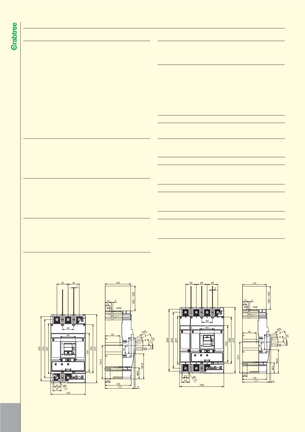
MAIN CONNECTIONS
I
The switching unit has a 32mm main contact which will accept up to M10
cable lugs, maximum width 30mm.
AUXILIARY EQUIPMENT OPTIONS
I
a) UVR
b) Shunt Trip
c) Auxiliary Switches
Shunt Trip Voltage Range
70%
Under Voltage Release Threshold 35%
Input Power of Auxiliary Releases < 3VA AC, < 3W DC
CURRENT CHARACTERISTICS
I
IR & II SET AT MINIMUM
CURRENT VALUE (A)
OHMIC VALUE
0.4
5
0.4
5
AMPS SECONDS SECONDS VOLTAGE SECONDS SECONDS
250
375A
375A
230V 0.613
Ω
0.613
Ω
400
600A
600A
230V 0.383
Ω
0.383
Ω
630
945A
945A
230V 0.243
Ω
0.243
Ω
IR SET AT MINIMUM & II SET AT MAXIMUM
250
1250A 575A
230V 0.184
Ω
0.400
Ω
400
2000A 920A
230V 0.115
Ω
0.250
Ω
630
3150A 1449A 230V 0.073
Ω
0.159
Ω
IR & II SET AT MAXIMUM
250
3125A 1500A 230V 0.074
Ω
0.153
Ω
400
5000A 2400A 230V 0.046
Ω
0.096
Ω
630
7875A 3780A 230V 0.029
Ω
0.061
Ω
IR SET AT MAXIMUM & II SET AT MINIMUM
250
1000A 1000A 230V 0.230
Ω
0.230
Ω
400
1600A 1600A 230V 0.144
Ω
0.144
Ω
630
2520A 2520A 230V 0.091
Ω
0.091
Ω
IEC 60947-2 copper conductors for test currents
350 – 400A 1 x 240mm
2
600 – 630A 2 x 185mm
2
400 – 500A 2 x 150mm
2
630 – 800A 2 x 240mm
2