


 78 / 91

TECHNI CAL DATA
N MCCB
78
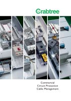
7T5A3IB
A1=200
A=100
C=50
H=20
C=50
C=50
B=210
B=210
D=100
E=142,5
G=40
G=0
F=0
7T4-5 FRAME MCCB s TECHNICAL SPECIFICATION
l
7T4-5 FRAME SPECIFICATION
I
• Specification IEC 60947-2 & IEC 60947-3
• Current Range 125 – 1600Amps
7T4, 125 – 1000Amps
7T5, 250 – 1600Amps
• Uie Rated Operation Voltage 690V AC
• Ui Rated Insulation Voltage 690V AC
• Rated Frequency 50/60Hz
• Icu (415V) Short Circuit Breaking Capacity 55/65kA
• Overload Adjustment 0.4 – 1.0 x Trip Unit
Rated Current
• Instantaneous Adjustment See Page over
• Ambient Range -40°C to 55°C
• Working Environment Both Dry and Tropical
Climates
• Mechanical Endurance 10,000 Cycles
7T4-5 FRAME FEATURES
I
The 7T4-5 circuit breaker consists of switching unit and either a range of
different rated electronic trip units, or a disconnector module. The modular
design provides the maximum flexibility as the user can decide not only the
rating but also the function, disconnector or protective device. With a wide
setting bandwidth electronic trip units offer unparalleled functionality.
AVAILABLE OPTIONS
I
• ST UVR
• Aux SW
• Rotary Handle (available on request)
• Padlocking
SHORT CIRCUIT BREAKING CAPACITY
I
Ue 7T4 Icu 7T4 Ics
7T5 Icu
7T5 Ics
220 V 85kA 45kA
85kA
45kA
415 V 65kA 36kA
55kA
36kA
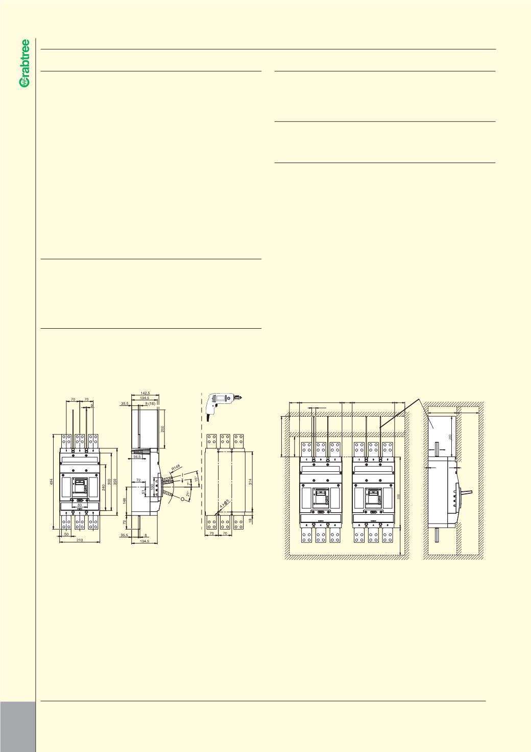
MAIN CONNECTIONS
I
The switching unit has a 50mm wide main contact which will accept either
busbar or cable lugs.
AUXILIARY EQUIPMENT OPTIONS (RETRO-FITTABLE)
I
a) UVR
b) Shunt Trip
c) Auxiliary Switches
Shunt Trip Voltage Range 70%
Under Voltage Release Threshold 35%
Input Power of Auxiliary Releases < 2.5VA AC, < 2W DC