


 81 / 91

81
TECHNI CAL DATA
MOTOR PROTECT I ON & CABL E SPREAD I NG
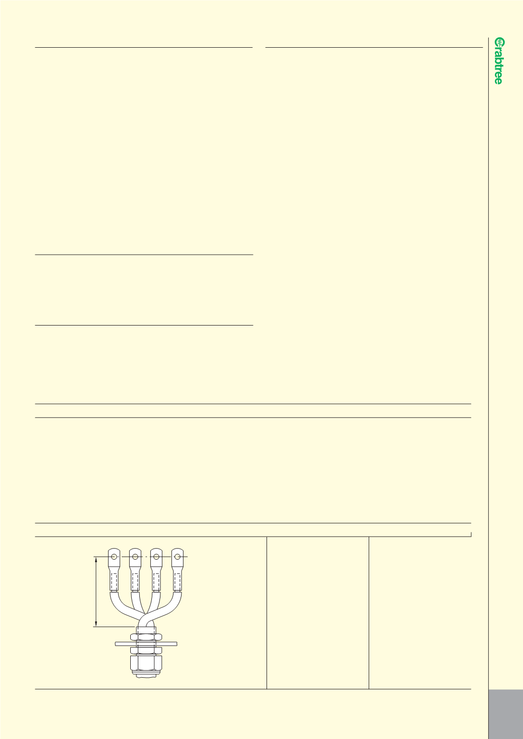
Cable Size Dimension ‘A’
(mm
2
) (mm
2
)
16 103
25 127
35 142
50 167
70 197
95 224
120 245
150 272
185 297
240 333
300 375
A
4 CORE TERMINATIONS, SPREADING ROOM
BS5372 SPREADING ROOM
The scope of BS5372 relates to dimensions which should be observed
in the design of cable terminations, having uninsulated conductor fittings,
for external cables on electrical equipment to enable the cables to be
connected satisfactorily.
The standard is based upon the use of compression type conductor
terminations and allows for the cores to be crossed within the terminal
enclosure because this combination requires more space.
The diagram and table below gives the dimensions quoted by this standard.
l
USE OF CAPACITOR BANKS
I
In general, reactive power compensation is used in order to reduce system
losses and voltage drops in the power distribution system. As a result, the
power fed into the system is used as active power and costs will be saved
through a reduction in the capacitive and inductive power factors.
A combination of fixed and central compensations are used depending on
the design of the low-voltage system and the loads involved.
Circuit breaker for protecting and switching capacitor banks
According to the relevant standards DIN VDE 0560 Part 41 / EN 60831-1 / IEC
70, capacitors must function under normal operating conditions with the
current having an r.m.s. value up to 1.3 times the rated current of the
capacitor. In addition, a further tolerance of up to 15% of the real value of
the power must be taken into consideration.
The maximum current with which the selected circuit breaker can be
constantly loaded, and which it must also be able to switch, is calculated as
follows:
I
N
max
= I
N
x 1.5 (r.m.s. value, r.m.s. current)
Important values for selecting circuit breakers
More detailed information in the technical data: Capacitor banks (Page 173)
Abbr.
Designation
Q
n
Capacitor bank rated power in kVA
V
N
Rated voltage of the capacitor
I
N
Rated current of the capacitor bank
I
N
max
Maximum expected rated current
I
i
Value for setting the instantaneous short-circuit release
I
R
Value for setting the current-dependent delayed overload release
The following applies:
I
N
= Q
n
/ 3 x V
N
I
R
= I
N
max = 1
N
x 1.5
I
i
> 9 x I
R
(minimum)
PRIMARY-SIDE TRANSFORMER PROTECTION
I
The circuit breaker as primary-side transformer protection
When switching on low-voltage AC transformers, the extremely high inrush
current peaks place special demands on the trip unit or on the making-
capacity of the circuit breakers if these are also used to switch the
transformer.
For most applications, an inrush current of 20 to 30 times rated operating
current is expected in practice and must be taken into account when
selecting the circuit breakers.
The maximum short-circuit current I
K
of the Powerstar circuit breakers 7T2 –
7T5 depends on the frame size. A circuit breaker in the lower setting range
must therefore be operated for primary-side transformer protection.
Example:
A transformer with 500A rated current; 20 times inrush current
Selected: 7T4 with ETU of I
n
= 800A; setting range 0.4 - 1 x I
n
= 315A to
800A
I
R
can be set at 500A; Instantaneous short circuit protection set at 12kA = 24
x current setting
Note
Switching the circuit breaker off
It is imperative to note that the minimum short-circuit current I
KMIN
in
accordance with VDE 0100 is switched off in every case using a protection
facility (e.g. circuit breaker).