


 181 / 211

T ECHN I CAL DATA
C I RCU I T P ROT ECT I ON
181
APPLICATIONS
l
RCBOs provide both earth fault and over current protection. The MCB
element of Starbreaker and Loadstar devices are available as Type B or Type C
making them suitable for domestic or light commercial applications. These
Type A Voltage dependent devices are single pole with solid neutral one
module wide (18mm) with a flying lead. During interruption of the neutral
conductor the protective function is guaranteed when FE and PE conductors
are connected. The use of Starbreaker and Loadstar 30mA RCBOs provides
independent RCD protection to individual circuits offering both the degree of
additional protection that may be required by Regulation 415.1 and the
minimum of inconvenience following a single earth fault (Regulation 314.1).
RCDs (RCCBs, RCBOs AND SRCDs)
l
INSTALLATION TESTING –
CAUTION
l
As Starbreaker and Loadstar RCBOs employ electronic components they
should be disconnected when carrying out the following tests on the electrical
installation:
(a) Earth fault loop impedance test
The load terminals should be disconnected if it is intended to parallel-out the
unit for test purposes.
It may incur damage if mains potential is maintained on the load terminals of
this unit after the trip mechanism has operated.
(b) Insulation test
Whilst RCBOs can withstand the effects of normal insulation testers without
damage, false readings may be given on the test instrument. For this reason
it is recommended that the device is disconnected during this test.
FAULT CURRENT SENSITIVITY
l
Semi-conductor devices are now incorporated in equipment used throughout
industry, commerce and in the home. Typically, the purpose of these semi-
conductor devices is for monitoring and controlling industrial equipment
eg speed controls for small motors and temperature controls, along with
extensive use in computers, VDUs, printers, washing machines, etc.
As the equipment is fed from the mains electrical supply, in the event of an
earth fault the presence of semi-conductors may result in the normal ac
waveform being replaced by a non-sinusoidal fault current. In some cases the
waveform may be rectified or chopped. These waveforms are said to contain
a pulsating dc component which can either partially desensitise or totally
disable a standard Type AC RCD.
International standards IEC 61008 (RCCBs) and IEC 61009 (RCBOs) divide
RCDs into two performance classes:
Type AC
RCDs for which tripping is ensured for residual sinusoidal alternating currents,
whether suddenly applied or slowly arising.
Type A
RCDs for which tripping is ensured for residual sinusoidal alternating currents
and residual pulsating direct currents, whether suddenly applied or slowly arising.
To ensure the correct level of protection, check for the following symbols:
TYPE AC
TYPE A
normal
pulsating
ac sensitivity
dc sensitivity
Crabtree RCCBs are available as both Type AC and Type A devices.
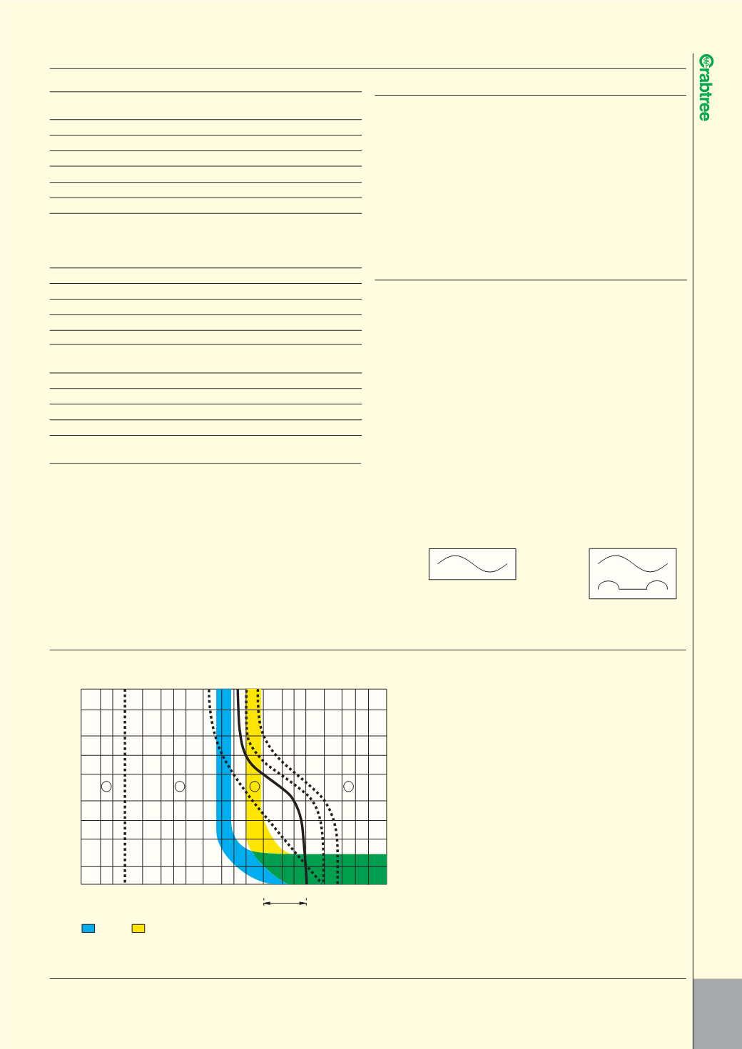
IEC PUBLICATION (60479) CURVES WITH CRABTREE RCD CHARACTERISTICS SUPERIMPOSED
l
TIME/CURRENT ZONES OF EFFECTS OF AC CURRENT (15–100Hz) ON PERSONS
Zone Physiological effects
1
Usually no reaction
4
In addition to the effects
effects.
of zone 3, probability of
ventricular fibrillation
2
Usually no harmful
increased up to 5%
physiological effects.
(Curve C2) up to 50%
(Curve C3) and above
3
Usually no organic
50% beyond Curve C3.
damage to be expected.
Increasing with magnitude
Likelihood of muscular
and time, pathyphysio-
contraction and difficulty
logical effects such as
of breathing, reversible
cardiac arrest, breathing
disturbances of formation
arrest and heavy burns
and conduction of
may occur.
impulses in the heart, and
transient cardiac arrest
without ventricular
fibrillation increases with
current magnitude and
time.
10,000
5,000
2000
1000
500
200
100
50
20
10
0.1 0.2 0.3 0.5 1 2 3 5 10 20 30 50 100 200 300 500 1,000 2,000
10,000
5,000
3,000
Current in milliamperes (RMS)
100mA
30mA
Typical current
Limits due to body resistance
at 230V
1
2
3
4
a
b
c
1
c
2
c
3
IEC 60479
Time in milliseconds
Technical Specifications (RCBOs)
up to 50A
Standards
EN 61009-1, IEC 61009-1
Approved acc.to
IEC/EN 61543
Rated voltages
Un
V AC
230(240)
Rated frequency
fn
Hz
50 ... 60
Rated currents
In
A
6, 10, 16, 20, 32, 40, 50
Rated residual currents
I
D
n
mA
30
Rated switching capacity
kA
6
Energy limitation class
3
Terminals /conductor cross-sections
Solid and stranded
mm
2
0.75 ... 35
Finely stranded, with end sleeve
mm
2
0.75 ... 25
Outgoing
mm
2
0.75 ... 16
Terminal tightening torque
Nm
2
Mains connection
Bottom
Mounting position
Any
Degree of protection acc. to EN60529
IP20 with connected conductors
Touch protection acc. to EN50274
Finger and back-of-hand safe
Service life
Test cycle acc.
switching
.
10000 actuations
to IEC/EN 61009 cycles
Storage temperature
˚C
-40 ...+45
Ambient temperature
˚C
-25 ...+45
Resistance to climate acc. to IEC60068-2-30
28 cycles (55˚C; 95% rel. air humidity
CFC and silicone free
Yes